4R were common impedance of loudspeakers in Europe at that time, 8R were not.
It is as simply as this.
No conspiracy theories required here
It is as simply as this.
No conspiracy theories required here
They said 200 watts »Sinus« power and 300 watts music power @ 4 Ω, requiring ±50 Vdc, and the same power @ 8 Ω when fed from ±65 Vdc. And yes, 4 Ω was the most common speaker impedance in Germany 50 years ago.
Best regards!
Best regards!
Not in France where vast majority of good quality speakers brands was 8R and rarely 4R, indeed i got a Dual CDV60 amplifier from my older brother, it was specced at 2 x 18W/4R only, and so was the CV120 that was specced at 4R, since i live close to Germany, where i got just today, i know a lot of german hardware, at the time there were brands producing decent compact stereos and all were using 4R speakers.4R were common impedance of loudspeakers in Europe at that time, 8R were not.
It is as simply as this.
No conspiracy theories required here
Agree that such brands as BO used 4R as well and it was due generaly to the fact that contrary to Japan, and even the US, there were no high voltage transistors available at reasonable cost from european component manufacturers, that was all 60V devices, guess that was one of the main reason the european audio industry was litteraly laminated in the late 70 with the few remaining manufacturers left using japanese sub contractors for most of their gear.
Last edited:

For the oldest brands , I agree, on the other hand, since the arrival of Siare, JmLab/focal and Davis a little later, the impedance became closer to 4 ohm in the 90s/2000s, afterward the average settled closer to 8.Not in France where vast majority of good quality speakers brands was 8R and rarely 4R
However, I have often encountered older speakers like Elipson (60s/70s), Cabasse (70s/80s) and other JMR very close to the 4 oms.
Small manufacturers like PEL or HRC were 8ohm
Not really. What you measure with your DVM is DC resistance, not impedance.
6 Ohm DC resistance is the average you will measure with 8 ohms impedance.
6 Ohm DC resistance is the average you will measure with 8 ohms impedance.
I do know the difference between DCR and impedance 😎
( I am referring to 'average' across the entire audio band of speakers > not drivers )
( I am referring to 'average' across the entire audio band of speakers > not drivers )
Last edited:
Some certain DIN standard here in Germany defines nominal impedance as a value 20 % higher than the impedance minimum, not it's average value, which certainly is much higher.
Best regards!
Best regards!
For the oldest brands , I agree, on the other hand, since the arrival of Siare, JmLab/focal and Davis a little later, the impedance became closer to 4 ohm in the 90s/2000s, afterward the average settled closer to 8.
However, I have often encountered older speakers like Elipson (60s/70s), Cabasse (70s/80s) and other JMR very close to the 4 oms.
Small manufacturers like PEL or HRC were 8ohm
I was talking of course of the 70s to the early 80s era, at the time any serious speakers were 8R, and IIRC Cabasse,
Focal or 3A where 8R mainly, i dont remember anything 4R from those times, eventually something could have
been specced 6R FI but that was surely because of an overdamped box to get tighter basses.
Isn't this some bit of hair splittig? Fact is about 40 to 50 years ago 4 Ω was the common speaker impedance at least here in Germany and maybe somewhere else in Europe. Period.
Best regards!
Best regards!
In North America the standard was (and still is ) 8R. Car audio was 4R for obvious reasons. These days you see a 6R nominal impedance rating on some speakers.
Most speakers I saw from Europe in the 1960's and 1970's were 4R. All I can do is relate what I did see. I did see 8R units from Europe as well, but most were 4R.
Most speakers I saw from Europe in the 1960's and 1970's were 4R. All I can do is relate what I did see. I did see 8R units from Europe as well, but most were 4R.
Yes, I meant +/- 70 VDC rails. They held up for many years running this way. I was assured by another engineer who worked for Motorola the devices were underrated.Did you mean ±70 Vdc? Never would have MJ2955's/2N3055's coped with supply voltages as high as this. Paralleling multiple devices also would not have helped either.
Anyway, about 50 years ago we could have mail ordered a 200 watt amplifier kit from a German dealer. The design featured two pairs of these devices, all in series! I never put an order, though...
Best regards!
Overrated by 200% or more (depending on datasheet). Okay ...
I wouldn't believe that for a second ort he part would be a different number. Many parts are graded and that determines part number.
I wouldn't believe that for a second ort he part would be a different number. Many parts are graded and that determines part number.
Yeah, Ill believe 3055’s running off +/-70 when I see it, no matter how many you put in parallel. Even the MJ15015/6 had trouble coping with it. That QSC used 6 pairs of 015/6 in parallel just to run off +/-57V. And it warned about 2 ohm use (4 ohm minimum specified, and they meant it). When I went to rebuild it with originals, the beta was so far out of whack between devices they wouldn’t share properly. Even with emitter resistors. Went to the 15024. And guess what - it would run on 2 ohms all day, and not take the drivers out doing it.
Motorola and On Semi referred to the MJ15015/16 as "Economy grade". In other words, garbage.
My experience with those mirrors yours. Beta all over the map, PNP and NPN beta ary far apart as a group. I used them for warranty replacements (rejecting most as I tested them first). Anything out of warranty got MJ1502x transistors.
My experience with those mirrors yours. Beta all over the map, PNP and NPN beta ary far apart as a group. I used them for warranty replacements (rejecting most as I tested them first). Anything out of warranty got MJ1502x transistors.
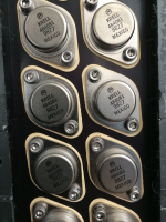
The important thing to realize about this is that an MJ15015 is a DIRECT DERIVATIVE of the 2N3055. Which already sucks, so it sucks harder. If you take the same basic transistor and just adjust doping to improve breakdown voltage (ie, from 100 to 200 - which is what actually happens) the beta FALLS. Like Mr. Scott said - you cannot change the laws of physics. If you want nice flat beta and higher voltage, you start some place different.
The same I had read long time ago (around the time the MJ15015 was released) in one of the first German PA power amp diy project with MJ15015/15016 - maybe in the magazine ELRAD - but I don't know exactly.
Because of this disadvantage, a very large number were used in parallel mode (8 pairs, if I recall right) with 1 ohm resistor for emitter degeneration.
The reason was according the circuit description that only an eighth of the current Ic flows in each individual pair, even at high load currents, and therefore the hfe value remains correspondingly high.
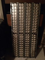
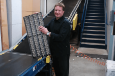
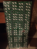
According the attached images from heatsinks of Krell's MRA (master reference amplifier) there are significantly more pairs operate in parallel mode (88 pairs for each channel).
Currently datasheet obviously now for both types:
https://www.mouser.de/datasheet/2/308/2N3055A_D-2309305.pdf
Because of this disadvantage, a very large number were used in parallel mode (8 pairs, if I recall right) with 1 ohm resistor for emitter degeneration.
The reason was according the circuit description that only an eighth of the current Ic flows in each individual pair, even at high load currents, and therefore the hfe value remains correspondingly high.
According the attached images from heatsinks of Krell's MRA (master reference amplifier) there are significantly more pairs operate in parallel mode (88 pairs for each channel).
Currently datasheet obviously now for both types:
https://www.mouser.de/datasheet/2/308/2N3055A_D-2309305.pdf
Attachments
Hi wg_ski,
I didn't want to know much about either part beyond what I ran into and could replace it with. They, as you say, sucked big time. It didn't matter how good your work was, performance would always be substandard. Completely agree, no matter how much you want the laws of physics to exempt your one case, it never does. They needed a different geometry and design of transistor entirely. Wasn't that the multi-emitter types that came next? I'm a little fuzzy on device history, I would have to look it up.
Hi tiefbassuebertr,
Over here in Canada, we mostly saw English kits and projects. The ETI amplifiers were unfortunately popular - because they were cheap. I can't tell you how many i had to fix. We always had designers using a ton of cheap power transistors in parallel for high power. Stupid. Always "PA amplifiers that never failed", sure.
One reason Krell and others used many power transistors in parallel was to distribute the heat from the high total bias current. To my mind, there is little point in running everything hot when you can get the same or better performance from enough devices for the power and load impedance without the high bias. All they are really doing is trying to get the delta I lower so it is more linear. Brute force and ignorance. I guess if you restrict yourself to a low overall transconductance amplifier you haven't got a choice. My response it that they choose the wrong path to follow. A ton of outputs is expensive and looks very impressive, you can spin a great story and charge more for it. So really we are talking about market differentiation. Not true performance or engineering skill.
Ever work on a Krell? Not fun. Soaks up bench time (= high labour charges), plus they are so hot, capacitors need replacement. Every 10 years is what is quoted around here. That's expensive man! Plus your running power costs, let's not go there.
That rings a bell, a dim memory.an MJ15015 is a DIRECT DERIVATIVE of the 2N3055
I didn't want to know much about either part beyond what I ran into and could replace it with. They, as you say, sucked big time. It didn't matter how good your work was, performance would always be substandard. Completely agree, no matter how much you want the laws of physics to exempt your one case, it never does. They needed a different geometry and design of transistor entirely. Wasn't that the multi-emitter types that came next? I'm a little fuzzy on device history, I would have to look it up.
Hi tiefbassuebertr,
Over here in Canada, we mostly saw English kits and projects. The ETI amplifiers were unfortunately popular - because they were cheap. I can't tell you how many i had to fix. We always had designers using a ton of cheap power transistors in parallel for high power. Stupid. Always "PA amplifiers that never failed", sure.
One reason Krell and others used many power transistors in parallel was to distribute the heat from the high total bias current. To my mind, there is little point in running everything hot when you can get the same or better performance from enough devices for the power and load impedance without the high bias. All they are really doing is trying to get the delta I lower so it is more linear. Brute force and ignorance. I guess if you restrict yourself to a low overall transconductance amplifier you haven't got a choice. My response it that they choose the wrong path to follow. A ton of outputs is expensive and looks very impressive, you can spin a great story and charge more for it. So really we are talking about market differentiation. Not true performance or engineering skill.
Ever work on a Krell? Not fun. Soaks up bench time (= high labour charges), plus they are so hot, capacitors need replacement. Every 10 years is what is quoted around here. That's expensive man! Plus your running power costs, let's not go there.
I think you refer to the ring emitter transistors that became the hot stuff of the nineties. Never got one, at that time I was on LatFETs.Wasn't that the multi-emitter types that came next?
- Home
- Amplifiers
- Solid State
- 2N3055 inside - commercial famous amplifier models, quasi complementary power output