In 1976 I built the 70W version of this amp from the RCA Power Circuits handbook.
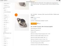
Although it lists the output devices Q6 & Q7 as 40636's, when I tried to buy them the distributor said they were NLA and replaced by the 2N3055.
So that's what I used and it worked out well.
Although it lists the output devices Q6 & Q7 as 40636's, when I tried to buy them the distributor said they were NLA and replaced by the 2N3055.
So that's what I used and it worked out well.
Attachments
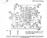

40636 was just one of many “selected 2N3055’s”. As the process matured, most of them would actually take 80 volt rails.
I had an old HH Scott with the singleton input (but other than that, same schematic). It had a 75V singke supply with output caps. It called for either 40636, 40411, or 2N3055. Mine had the 3055’s. Drivers were what blew - and I ended up using MJE181/2 because the originals were NLA. I ran with the original set of outputs, which survived the fault. Motorolas wouldn’t have.
I had an old HH Scott with the singleton input (but other than that, same schematic). It had a 75V singke supply with output caps. It called for either 40636, 40411, or 2N3055. Mine had the 3055’s. Drivers were what blew - and I ended up using MJE181/2 because the originals were NLA. I ran with the original set of outputs, which survived the fault. Motorolas wouldn’t have.
The PDF don’t want to open on this old machine. But if I recall it, it was 90 volt VCER instead of only 70. I think 40636 was 80 volt VCEO. I used to have that whole old data book, but it disappeared eons ago. Oldest I have now is the 1982 Harris power device book. And the 2N3053/4/5 pages (and front cover) are long gone. A few fell off and got lost every year. My first page now is the 2N3439/3440/4063/4064 page. And all the 5-digit house numbers were no longer in use at all.
My RCA databook (falling apart but all pages still there) says 40636 Vcer=95V.
For some reason best known to themselves RCA relabelled the 40636 as an RCA1B01. But a moot point because that's gone too now.
Quite a few Moto transistors (Onsemi) like the MJ15003/4 would work in these old amps. Probably without mod but a better approach might be to improve the bandwidth. (MJ15003 fT=2MHz compared with 2N3055 (H type) which maybe managed 1MHz.)
Hi wg_ski,
My databook clearly lists emitter-collector breakdown as 60 VDC, base open. Same for the Lambda (power supplies) data I have somewhere. I always go by that rating, and whatever the listed breakdown is on any transistor. Anyway, two original sources agree on that number. I believe it is the original rating.
My databook clearly lists emitter-collector breakdown as 60 VDC, base open. Same for the Lambda (power supplies) data I have somewhere. I always go by that rating, and whatever the listed breakdown is on any transistor. Anyway, two original sources agree on that number. I believe it is the original rating.
I found some place actually selling the 1B01 surplus, and it lists 95 Vcbo. Ive never actually run into those in an actual amp, but every manner of 5 digit #.
When fixing those old amps my usual inclination is to put in something better than a 2N3055, like a 2N5631. I have a pretty good stash of the NPNs and PNPs - in the old aluminum case. Could use MJ15024’s, but if it don’t need that I save them for what does.
When fixing those old amps my usual inclination is to put in something better than a 2N3055, like a 2N5631. I have a pretty good stash of the NPNs and PNPs - in the old aluminum case. Could use MJ15024’s, but if it don’t need that I save them for what does.
Attachments
I have never seen any Vceo spec. for the 40636. As tiefbasseubertr posted, the datasheets only ever mentioned Vcer. The 2N3055 was always spec'd at 60V Vceo, 70V Vcer and 100V Vcbo. So the 40636 devices only had to be picked for those which met the high Vcer rating. The Vceo could well have stayed at 60V, but was not published. At least in the databooks I have.
I suspect that Vcbo rating meant that many epi base devices had to have been built to a higher Vceo (at least in the early days) to meet that spec, which is why people like Maplin got away with sticking a high voltage on their amp. as they used the complementary pairs. IIRC they were Moto back then as a preferred supplier.
As I posted a few times, all the ST and Moto /ONsemi devices I have measured all had over 80V Vceo. (These are probably the most recent generation though). ST have given up on metal cans, but supply a TIP3055/TIP2955.
Some manufacturers did not obey that 100V Vcbo spec for their imitation devices which may have got a bad reputation in some cases.
Any few vintage amp brands reduce their supply voltage far to the maximal ratings for Vce according datasheet to get more reliability. To get the wanted output power the use of bridge mode was realized (eg. the Hadley 622 go toHi wg_ski,
My databook clearly lists emitter-collector breakdown as 60 VDC, base open. Same for the Lambda (power supplies) data I have somewhere. I always go by that rating, and whatever the listed breakdown is on any transistor. Anyway, two original sources agree on that number. I believe it is the original rating.
https://www.usaudiomart.com/details/649464082-hadley-622-power-amp/images/2002692/
and for schematic to post #22 here).
Partly with a massive amount of BjT's in parallel mode.
Check out in this case my question in post # 57 under
https://www.diyaudio.com/community/threads/2n3055-the-early-years.382690/page-3#post-7471276
Last edited:
Not many were willing to run 3055’s way the hell under vceo, because 60 volts doesn’t give that much power. Even Hadley’s bridge amp is just under - as is the old NAD by a fraction of a volt. The NAD‘s only real problem was the omission of emitter resistors, which reportedly improved the crossover distortion spectrum - but is really a no no unless it’s on an IC. It’s not the voltage it runs at that was the problem. But they got away with it, as did most manufacturers who had their 3055-oids selected to “run“ at 80 volts. With varying degrees of success. Some of those old Peavey amps were damn reliable
Motorola’s complementary epi process could not always support even 60 volts. They had a LOT of 40 volt rated devices back in the old days. Beta was through the roof on some of them. Once their stuff could reliably do 120V, their stuff just took off. Eventually what they were making as a “2N3055” could do that.…. most of the time. That’s what was in the Maplin amp. But the 40-ish volt second breakdown point never moved, so it’s time to parallel a couple up. That helped with the beta droop. Most +/-55 supplies using a transformer will drop to just north of +/-40 under a 3 or so amp average DC load, and that gives right at 200W at 4 ohms. That could be ok for a DIY kit. Not in production. In the kit, one could substitute something more appropriate.
The 100 volt Vcbo is what the old Homo process would do - collector to base. They got leaky when you went collector to emitter, and that’s where the down rating to 60V came from. Kinda like the old Ge devices. ICEO under that condition was something riddikulus like 200 mA! Most everything was better - but yield is everything to a semiconductor house!!!! But the JEDEC specs for a “2N3055” got carved in stone - and it was up to the other guys to “meet” them. When they could meet the published spec, they could market their device as a “2N3055”. Even if the median characteristic suggested something different. That’s what happened with the Motorola - especially as their epi process got better.I suspect that Vcbo rating meant that many epi base devices had to have been built to a higher Vceo (at least in the early days) to meet that spec, which is why people like Maplin got away with sticking a high voltage on their amp. as they used the complementary pairs. IIRC they were Moto back then as a preferred supplier.
As I posted a few times, all the ST and Moto /ONsemi devices I have measured all had over 80V Vceo. (These are probably the most recent generation though). ST have given up on metal cans, but supply a TIP3055/TIP2955.
Some manufacturers did not obey that 100V Vcbo spec for their imitation devices which may have got a bad reputation in some cases.
Motorola’s complementary epi process could not always support even 60 volts. They had a LOT of 40 volt rated devices back in the old days. Beta was through the roof on some of them. Once their stuff could reliably do 120V, their stuff just took off. Eventually what they were making as a “2N3055” could do that.…. most of the time. That’s what was in the Maplin amp. But the 40-ish volt second breakdown point never moved, so it’s time to parallel a couple up. That helped with the beta droop. Most +/-55 supplies using a transformer will drop to just north of +/-40 under a 3 or so amp average DC load, and that gives right at 200W at 4 ohms. That could be ok for a DIY kit. Not in production. In the kit, one could substitute something more appropriate.
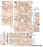
Talking about the RCA 40636, I just demolished a junk Wega 3220 hifi console yesterday which has a quasi-complementary output stage with the 40636 devices. The unit came with the original service manual, so hereby a scan of the output stage. Rail voltages are +/- 43V, which each rail to each output stage individually fused at 3.15A. I have no particular future project for the 40636 devices, so if anybody needs them they are available, as well as the original service manual.
This circuit is very close to RCA's own circuit in the RCA1B01 datasheet (also attached).
Baxandal diode already incorporated; but the circuit would benefit by constant current sources in the input and VAS stage.

This circuit is very close to RCA's own circuit in the RCA1B01 datasheet (also attached).
Baxandal diode already incorporated; but the circuit would benefit by constant current sources in the input and VAS stage.
Attachments
Last edited:
If anyone can make use of them I have two sets of 2N3055 & MJ2955 pairs that I've had here for probably 40yrs. Yours for the cost of the postage.
Thank you for posting this schematic and datasheets.Talking about the RCA 40636, I just demolished a junk Wega 3220 hifi console yesterday which has a quasi-complementary output stage with the 40636 devices. The unit came with the original service manual, so hereby a scan of the output stage. Rail voltages are +/- 43V, which each rail to each output stage individually fused at 3.15A. I have no particular future project for the 40636 devices, so if anybody needs them they are available, as well as the original service manual.
This circuit is very close to RCA's own circuit in the RCA1B01 datasheet (also attached).
Baxandal diode already incorporated; but the circuit would benefit by constant current sources in the input and VAS stage.
View attachment 1244637
One detail in the Vbe multiplier of the power amp unit from Wega's 3220 hifi console is very special: R409 (390K).
This I haven't see before.
What is the aim of R409 ?
Hi,Talking about the RCA 40636, I just demolished a junk Wega 3220 hifi console yesterday which has a quasi-complementary output stage with the 40636 devices.
This circuit is very close to RCA's own circuit in the RCA1B01 datasheet (also attached).
why did you demolish this design icon? And what did you do with it's Dual 1229 record changer?
Anyway, yes, the power amplifier appears to be right from the contemporary RCA appication notes, as well as the RIAA amplifier which fell out of the Fairchild µA739 databooks.
Best regards!
Good question, I got intrigued myself after you mentioned it.Thank you for posting this schematic and datasheets.
One detail in the Vbe multiplier of the power amp unit from Wega's 3220 hifi console is very special: R409 (390K).
This I haven't see before.
What is the aim of R409 ?
Have to figure that out !
Because the Dual record player was already taken out by previous owner for his own project; and the rest of the unit was badly damaged all over. I even tried to sell it for 20 euros on local auction, but after 2 months I gave up and decided to take the good parts out and have the rest properly recycled.why did you demolish this design icon? And what did you do with it's Dual 1229 record changer?
B&O BeoCenter 3500 used 2N3055.
It did, and it has the same particular resistors that tiefbassuebertr mentioned for the Wega unit.
Well, if you spot it; B&O schematics are brain gymnastics to read
- Home
- Amplifiers
- Solid State
- 2N3055 inside - commercial famous amplifier models, quasi complementary power output