I will construct Ivey's schematic see if there is any things that i would like to change dress it up with a beefy power supply and give it for evaluation to phono people ...
I will post my findings here
Kind regards
Sakis
I will post my findings here
Kind regards
Sakis
I am constructing in a vero board as we speak couple of things i can tell for sure
---In minimalistic circuits like that PSU plays a very important role
---When it comes to the RIAA net work except quality and tolerance i noticed variations depending on the make of the part regardless of the value
Working on it pictures in a few hours
Kind regards
Sakis
---In minimalistic circuits like that PSU plays a very important role
---When it comes to the RIAA net work except quality and tolerance i noticed variations depending on the make of the part regardless of the value
Working on it pictures in a few hours
Kind regards
Sakis
Got my self 50 transistors first thing in the morning made by ST from Malaysia
To my very surprise the first 30 i measured had a very steady hfe from 280 to 305 ...that was odd only once in my life faced this with a stock of BC 557 that was probably military specs and was all of them in the same hfe between +-10%
Ivey new what he was talking about i think ...
To my very surprise the first 30 i measured had a very steady hfe from 280 to 305 ...that was odd only once in my life faced this with a stock of BC 557 that was probably military specs and was all of them in the same hfe between +-10%
Ivey new what he was talking about i think ...
Today transistors can be a great surprise, thanks for keeping Ivey's memory, a good man transistor phono preamp circuit.
looking forward for those fotos and impressions!
looking forward for those fotos and impressions!
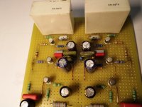
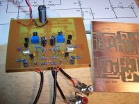
The board is working on the first click ...No mistakes that i have noticed .
I decided to go with regulated rails and a different power supply for each ch ... have made couple of things different there ( i like my own style of regulation based on LM 317 ) but with one or two twists.
Gained plenty of experience on that while trying to find a more audiophile psu yet simple for my DOZ There learned that the DOZ is a far better preamplifier if supplied properly ...
couple of things
1) yes the board is the same neat as is on the top both on lower side
2) yes both trimmers increase supply if turned CW😀😀😀
3) I will install termination options on the input plugs depending on the customer that is going to listen to the phono stage and his pickup settings
4) No changes from the original circuit except minor changes in the RIAA network ( very minor ) and also there mix matching of the capacitor types produced slightly different results kept the original values almost and trusted my ears for the rest
5) input capacitor was done with a MKT 6.8/ 160 ... I don t like that but it was the only thing available at the shop on a Friday afternoon and output capacitor was 47/63 extremely low ESR and bypassed with 1.0 ufd film capacitor ....
My intention is to see if there is any noises after the board is housed in a metal case and i will keep the options open to supply from a CT depending on the noise if any produced ...
Then i will listen to it ... give to a few phono enthusiasts , customers and friends that normally own sophisticated systems to see how it will turn up .
Here is some photos of the board and in a couple of days new one will come up with the complete construction.
Kind regards
Sakis
Attachments


a bit of History fun to read in a way power supply related ...
I am 48 ...so in my younger times like when i was 16 it was the Golden years of Disco .Greece , Athens is a small place ...we had real clubs at the time filled with 2000 ppl every day Good old time pre crises stories ...
We had also many places that belong to the region ""wana be a big club when i grow up """ meaning small local mini clubs that actually imitating the operation of the big clubs in a far more smaller scale ...
All of them had dimmers inside Nobody thinks about DMX or even 0-10V controls This is the 80's people none of these things was existing at the time and if was far to expensive for a wana be club .
Dimmers had 2 major problems
one produced plenty of buzzzzzzz in the audio systems
Two was impossible to drive NEON lights through the HV transformers of the time since if you try to dim with a shelf oscillated dimmer the transformer usually "jumps" 50 cm of the ground from the oscillation and the NEON flickers to anything lower than 80%
At the time and when i was 16 i actually made a fortune selling to wana be clubs dimmers that could do both
One i was installing dimmers that where made far more simple than the ones already had and often i skipped the inductor in the output But during my installation i was removing all the wiring and mistakes that was made in the simple audio system of the club resulting all available forms of ground loops ..>See the Buzz was coming from the audio installation and not from the dimmer
As about NEON drive the solution was so dirt simple what was driving the dimmer nuts was the transformer as a load ...so a resistive load parallel with the transformer in small application a block of parallel resistors of 17W and in bigger ones a simple bulb of 60-100W in parallel with the primary side of the HV neon trafo made the dimmer work properly ...
end of history ...
Kind regards
Sakis
hook it up for my second quick listening and the first click says that high is not what is supposed to be ...will look again and check my circuit and let you know
Kind regards
Sakis
Kind regards
Sakis
hook it up for my second quick listening and the first click says that high is not what is supposed to be ...will look again and check my circuit and let you know
Kind regards
Sakis
Are you using my revised circuit?
So you now know why you have problem 😉
Original circuit doesn't work. Ivey itself said he made by memory. I revised entire circuit, especially in feedback network, where 1uF and 1k were totally WRONG. If you want to really use that circuit, use my revision, except for the output resistor that have to be 470k (47k only for simulation).
Robertor, how is it going?
With original circuit you have less gain, less riaa precision, more noise, more distortion, less acceptance. You choose but i believe in the heart that now you are not satisfied.
Well NO big time
Original circuit works just fine there is a mistake on the input capacitor is supposed to be 1nf not 1 uf and probably some error in the RIAA circuit that will be probably 2 minutes of work to trace ...
I will continue with Ivey's circuit as started and see how far i will go after the circuit works properly as was the original idea
The point is to go from a working circuit from Ivey to evaluate both his sayings but also next to other phono stages of the same magnitude....
Obviously there can be a million other phono stages each and every one of them with pros and cons here we talk about Iveys phono stage
Let me finish and i will let you know
this is interesting - for solid state I've generally preferred single ended transistor phono stages over those made with op-amps.
my schematic is only an optimized version of Ivey's original that has many mistakes (biasing, low part of riaa, global feedback, ecc), typical of old projects made with paper and pen. Then the (bad) memory did the rest. My little work was because i liked Ivey and his original idea, so it was a tribute. I made it to build in the correct way and to listen to the music, but now i realize you're just experimenting... Even 1nF in feedback network with 1k (it's not an input capacitor!!!!) will cause a boom in upper bass region and a fast roll-off below.
Enjoy your hobby but don't say that original circuit works fine because it's NOT true!
Enjoy your hobby but don't say that original circuit works fine because it's NOT true!
Last edited:

Gianxdiy:
I will build your circuit and Ivey's circuit as well. I will compare the two. I am sure that your circuit will be a mark improvement over Ivey's circuit. But one must keep in mind that Ivey's circuit was designed when stereo was new concept, and he only had experience, pen, paper, and RIAA figures. They did not have the tools that we have today.
Yet, in truth, it all comes down to sound.
Missing Sound
The circuit shown by Salas in No 109. Has it been shown with better calculations for components? I was thinking to try it with different transistors. Of what I easily have BC337 25 seems OK. I think it is low noise. I might have some BC 337 40 . Maybe some BC 550 C also.
Ivey's
robertor u left us hanging.What's the verdict on gianxdiy version of Ivey's riaa.Feedback is appreciated.Many thanks.
east electronics an update is appreciated.
gianxdiy could I use the 2n4401 as Ivey's grandson? Would it be a drop in replacement.PS could u do a sim.?
Yes I'm late to the thread but thanks to Ivey and his grandson.
Well it's been a while but I finally built Ivey's pre-am. I put a 4K7 trimmer instead of the fixed resistor so I could balance the outputs. I also took out the
1uF cap in the input. I'm not going to say that this is the best sounding pre I've ever heard but it's in the top 5%. I made my own pc board layout because I may add a tone control section in the future. The layout is there, I just have to mount the components. All total I spent about $20 usd. Not bad at all.
Bruce
Attachments
Bruce
That is real pretty stuff.
The broads are great looking, with a good ground plane.
What layout software did you use? I use Express PCB.
Also, the use of the pot, was a grand idea.
Ivey would be proud to see it, if he was here.
That is real pretty stuff.
The broads are great looking, with a good ground plane.
What layout software did you use? I use Express PCB.
Also, the use of the pot, was a grand idea.
Ivey would be proud to see it, if he was here.
The broads are great looking, with a good ground plane.
I'd be careful in telling them that 😉
- Home
- Source & Line
- Analogue Source
- 2N2222A phono preamp