OK people,
Here's my last post on Ivey's 2N2222a PRE AMP.
After having success using plastic 2N2222a transistors, I decided to give
Gianxdiy mods a try but using metal case 2N2222a. I did another PC board and used all the component values listed in post #120.
On power up there was no smoke or sound coming out of the board. I made some voltage check and found that R1 6.8K was the problem. I dropped the decimal and put a 68K resistor in and great sounds came pouring out of my headphones. In hind sight I remember having to change the value of R1 in Ivey's
original amp. I did some transistor rolling once the board was working. I used 2N2222a, 2N3904 and 2N4401. They all sounded the same. I did not do scientific measurements, just listening test.
Attachments
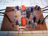
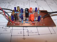
I must say that it is a great looking board.
Will you be posting the drawing of your project and the mods you made.
Missing Sound
Will you be posting the drawing of your project and the mods you made.
Missing Sound
Bruce:
What will you mount the board in, and what is your decision on a power supply for it?
I like to know what your ideas are.
I purchase a lot of 10 2N2222A, and the hfe, was all over the place. And just like Ivey stated. The only way to go, was to use JAN 2N2222A, because I got some off of Ebay, the price was high I might add. The hfe was stable at 294 to 298.
So the highs will be Q1 and the others using the lower hfe.
I will build my unit in the coming months, and I will post photos. Just waiting for the parts to arrive from Ebay. About 20 to 30 days.
Hi Missing Sound
I don't plan a major project for this pre-amp. I did it just out of curiosity, to see what the results would be. If I were to put it into an enclosure I would use something like this:
Aluminum PCB Instrument Box Enclosure Electronic Project Case DIY 100 76 35mm | eBay
of the correct size. My pc board is 3X4 inches. As far as for a power supply, A wall wart works well, 12 - 20vdc. This build is as shown in post #120 except for R1. 68K worked for me. Its a great sounding pre-amp.
Let me know how your projects looks and sounds.
Bruce
Attachments

pre phono 2n2222
I mada a lot of prephono and I'm curious to construct your 2n2222 pleasd sen to me pcb
I mada a lot of prephono and I'm curious to construct your 2n2222 pleasd sen to me pcb
Just for fun, I have taken Giandx's diagram from posting #120 and simulated it in LTSpice.
To start with, it didn't work because the 12K collector resistor of the second transistor was way too large. Changing this to 6K started the whole thing the way it should.
Second point is the 10K resistor at the input, which is only producing noise and should be reduced to 100 Ohm. By doing that with the cart connected, the A-weighted noise goes from -68dB to -70dB ref 5mV@1Khz.
As a third point, the two 100uF caps are too small and restricting the LF response.
I changed them into 150uF and 300uF resp to get a -3dB point at 10Hz.
And as a last point, input resistor should not be 47K but 86K because the whole input circuitry,also roughly 86K, is in parallel.
Hans
I was not happy with the sensitivity for certain components, and the 100pF at the input was also quite unwanted, being in parallel to the cable capacity.
So I went back to the original posting and tried to get as close as possible.
The base of the input transistor was short circuited to a 1uF cap, where I think the 47K input resistor should have been, this was obviously an omission.
The second transistor was running on a very low current, so this was increased to somewhat above 2mA.
I tuned the gain to 40dB, which is the usual gain for an MM preamp.
The 10K input resistor, producing just noise, was kept at 100 Ohm as before.
So this is the final design that I came to, having an overload margin of more than 20dB, and a distortion at 5mV@1Khz below -90dB.
Of course the emitter follower by means of the third transistor has to be added yet, but this is very uncritical.
Hans
R8-R9-C5 in #171 set the AC gain higher than the DC gain.
Some readers may not have seen the alternate topology. Nelson Pass used it in his NS-10 preamplifier in the mid-1970s. Two resistors and one capacitor, but now the resistors are in series rather than in parallel. It's a fun little exercise to dream up reasons why N.P. might do it the red way.
_
Some readers may not have seen the alternate topology. Nelson Pass used it in his NS-10 preamplifier in the mid-1970s. Two resistors and one capacitor, but now the resistors are in series rather than in parallel. It's a fun little exercise to dream up reasons why N.P. might do it the red way.
_
Attachments

Resistor current / excess noise? Metal films weren't necessarily a given back then.It's a fun little exercise to dream up reasons why N.P. might do it the red way.
Nelson's way: AC gain and DC operating point of the first transistor are separated - you can adjust the AC gain independently of the DC operating point. With Hans' way, they are interactive - you have to adjust the DC operating point according to the total resistance (R1 + R2).
I used Hans's way in my 4 transistor 'Bonsai' MM preamp (design dating back to 1979 based somewhat on the Dinsdale topology).
I used Hans's way in my 4 transistor 'Bonsai' MM preamp (design dating back to 1979 based somewhat on the Dinsdale topology).
per schematic, r10 = 1k?
I was not happy with the sensitivity for certain components, and the 100pF at the input was also quite unwanted, being in parallel to the cable capacity.
So I went back to the original posting and tried to get as close as possible.
The base of the input transistor was short circuited to a 1uF cap, where I think the 47K input resistor should have been, this was obviously an omission.
The second transistor was running on a very low current, so this was increased to somewhat above 2mA.
I tuned the gain to 40dB, which is the usual gain for an MM preamp.
The 10K input resistor, producing just noise, was kept at 100 Ohm as before.
So this is the final design that I came to, having an overload margin of more than 20dB, and a distortion at 5mV@1Khz below -90dB.
Of course the emitter follower by means of the third transistor has to be added yet, but this is very uncritical.
Hans
View attachment 604892
ok so if i get the degenerative feedback scheme (ignoring the RIAA elements for the moment), you're doing a little AF local degenerative feedback at R1 while R10 is essentially about rolloff nearing DC.
Last edited:
The only purpose of R10 is to provide the input transistor Q1 with a DC setting.ok so if i get the degenerative feedback scheme (ignoring the RIAA elements for the moment), you're doing a little AF local degenerative feedback at R1 while R10 is essentially about rolloff nearing DC.
R1 determines the overall AC gain and R2/C3 are for roll off nearing DC.
Hans
Hi there, after a long reading of this post i've decided to build this phono preamp from Ivey.
I'm not new to electronics but unfortunately i've not basis of electronics theory, so if I come to modify some circuit for some reason I always need an outcoming expert's help.
As in this case, I would need to lower the VCC from 30V. to 13V.
I expect to change some resistor's values, but what they are?
Or maybe I can build it with the original values without changing anything?
I saw there's a Zener ov 20V. in the circuit so i deduce that only reducing VCC is not a good choice...
Does anybody want to help me in this purpouse??
I thank you in advance and I take the opportunity to salute you all 'cause this is my very first post!!
Jame
- Home
- Source & Line
- Analogue Source
- 2N2222A phono preamp