AJT,
The common "full wave" doubler is, in fact, 2X 1/2 wave rectifiers wired back to back. That setup would give you different ripple frequencies for the plate and g2 supplies.
A highly efficient, truly full wave, multiplier setup is available. Not at all surprising is the cost involved. VMI's web site is having trouble. So, I'll link (hopefully) the schematic page soon. Think in terms of stacked 4 diode bridges that are connected to the rectifier winding via capacitors (2 caps./bridge). I would not consider anything except AC rated film parts for those "arm" position capacitors.
I am thinking about a voltage doubler option for higher B+ for the driver stage - I see you are using a totem pole so the higher voltage makes perfect sense. I was thinking of higher B+ so that I could use a larger resistive load for a simple high Ri triode like 12AX7. This would allow the 12AX7 to operate more like the classic L-W design where people have reported very good results using the 12AX7. Some people have not been so happy with this driver. Apart for ability to flow current I think one reason for that is because you need a high load impedance to get the good linearity that the 12AX7 is capable of (Merlin liked the 12AX7 linearity a lot!). I also will try a triode-wired pentode driver stage.
Bigun
12ax7 can definitely be linear but it's no driver. You need a low impedance driver to get really good damping. The differences are profound.
Ian
Member
Joined 2009
Paid Member
post #308: Edcor XPWR105what is the part number of your power traffo
I disagree with you, there are many very well regarded 2A3 amplifiers with so-called wimpy drivers12ax7 can definitely be linear but it's no driver.
see: http://www.diyaudio.com/forums/tubes-valves/212673-why-do-wimpy-drivers-2a3-work-well-they-do.html (post #8)
http://www.seriousstereo.com
http://www.6moons.com/audioreviews/fi/mono.html
Last edited:
12ax7 can definitely be linear but it's no driver. You need a low impedance driver to get really good damping. The differences are profound.
ZVN0545A to the rescue. 😀 DC coupling the FET to the 'X7 triode is a "no brainer". What was once quite wimpy now has some cujones.
Last edited:
AJT,
The common "full wave" doubler is, in fact, 2X 1/2 wave rectifiers wired back to back. That setup would give you different ripple frequencies for the plate and g2 supplies.
A highly efficient, truly full wave, multiplier setup is available. Not at all surprising is the cost involved. VMI's web site is having trouble. So, I'll link (hopefully) the schematic page soon. Think in terms of stacked 4 diode bridges that are connected to the rectifier winding via capacitors (2 caps./bridge). I would not consider anything except AC rated film parts for those "arm" position capacitors.
the Japs were doing it for ages.....i have seen sansui's and pioneers using voltage doublers in their tube amps, they must have seen something good
about that psu, and so do i....
ZVN0545A to the rescue. 😀 DC coupling the FET to the 'X7 triode is a "no brainer". What was once quite wimpy now has some cujones.
agree, in my case the 6cg7 was enough...
Bigun, this is what i would do with your transformer and psu....
you do not have to do all at the same time...
1. series resistor with the traffo secondary
2. RCRC filtering after the choke....start with one section and then add as needed
3. values shown are estimated, actual values can be different...
you do not have to do all at the same time...
1. series resistor with the traffo secondary
2. RCRC filtering after the choke....start with one section and then add as needed
3. values shown are estimated, actual values can be different...
Attachments
Sure, add a Mosfet follower is one way to solve the whimpy driver problem.
I tried it too.
Better still use no whimpy driver and no follower. Use a triode strapped pentode.
Ian
I tried it too.
Better still use no whimpy driver and no follower. Use a triode strapped pentode.
Ian
Lots of choice for triode strapped pentodes. E180F E280F E810F DA3 and others work well.
Feel free to check russian equivelants which are cheap and good.
Perhaps Eli's Mosfet follower is cheapest. I even tried mosfet bootstrapped, which helps get the whimpy triode nice and linear....
As you know from my previous posts, bootstrapped follower works too if you want to avoid the Mosfet.
But after trying SO many things, I prefer the triode strapped pentode with CCS.
Ian
Last edited:
I disagree with you, there are many very well regarded 2A3 amplifiers with so-called wimpy drivers
see: http://www.diyaudio.com/forums/tubes-valves/212673-why-do-wimpy-drivers-2a3-work-well-they-do.html (post #8)
Welcome to Serious Stereo. The ultimate SET amplifier, passive attenuator, High Effienciency Speakers, Vacuum tube amplifier, tube amplifier, single-ended amplifier, triode amplifier
6moons audio reviews: Don Garber's Fi 2A3 Monos
That is the lovely thing about DIY. But I have built ones exactly like those, and many variation of them too.
I didn't like them. Things got better with a follower. Then bootstrapped follower. Then many different MOSFET followers. The one Eli notes is ok for 12ax7 of course.
But then I got annoyed with the follower. Its certainly better than whimpy driver alone, but I wanted to get single ended 2a3 sounding as good or better than my 2a3 PP, which has no follower circuit..
So then I ended up with triode strapped pentode. Its worth trying. 😉
Member
Joined 2009
Paid Member
AJT,
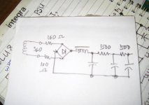
You'll get no argument about the 2 diode "full wave" doubler from me. As it was good enough for Hegeman, McIntosh, Fisher, et al., it's quite good enough for me and I frequently employ it.
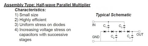
My concern lies with a multiplier that is tapped for more than 1 voltage. Having the same ripple freq. in all rails strikes me as being "best". The simplest, efficient, multi-tapped multiplier that exhibits a common ripple freq. is the 1/2 wave parallel configuration. Use good sized stage caps. and LC or RC sections at the taps and the results will be satisfactory.
You'll get no argument about the 2 diode "full wave" doubler from me. As it was good enough for Hegeman, McIntosh, Fisher, et al., it's quite good enough for me and I frequently employ it.
My concern lies with a multiplier that is tapped for more than 1 voltage. Having the same ripple freq. in all rails strikes me as being "best". The simplest, efficient, multi-tapped multiplier that exhibits a common ripple freq. is the 1/2 wave parallel configuration. Use good sized stage caps. and LC or RC sections at the taps and the results will be satisfactory.
Attachments
post#145
yup. That's a much better plan. Strap G3 to the cathode if you're not sure.
That is the lovely thing about DIY. But I have built ones exactly like those, and many variation of them too.
I didn't like them. Things got better with a follower. Then bootstrapped follower. Then many different MOSFET followers. The one Eli notes is ok for 12ax7 of course.
But then I got annoyed with the follower. Its certainly better than whimpy driver alone, but I wanted to get single ended 2a3 sounding as good or better than my 2a3 PP, which has no follower circuit..
So then I ended up with triode strapped pentode. Its worth trying. 😉
indeed, one man's food can be another man's poison...
as diy'ers put it, one man's junk can be another man's treasure...
Member
Joined 2009
Paid Member
I have put the choke back on the chassis. I found that the varnish has all but fixed the problem - good call you guys in pushing me to try it. I've removed C1, it's a pure choke-input supply now.
The temporary B+ load resistor gets way too hot fast so I wasn't able to do much. So I decided to wire up the power tubes to provide a real load for the B+. I installed another Octal socket.
Both sockets are wired up with heaters, g2 is connected to plate through 100R or 200R resistors (i.e. triode-wired). Cathodes are wired to ground through 1k resistors and both g1 have 1k or 2k2 stoppers at the socket pins. As I have only one OPT on the chassis I have grounded the input of one tube, the other is wired with a 560k grid leak resistor to ground. No Ck's installed yet.
This set up gives me a chance to check that all is well at d.c.
Powered up I get 317V B+ under load. I get 44.7V / 47.7V across Rk, so I'm running at 44.7mA / 47.7mA respectively.
It's a start - nice to see something glowing.
Attachments

I already hear a distant mono sound...
Got to love that chassis full of cheese holes! Awesome Bigun.
Got to love that chassis full of cheese holes! Awesome Bigun.
Member
Joined 2009
Paid Member
I already hear a distant mono sound...
You do indeed 😀
I made a hybrid amplifier, my first ever... so I wired up the RCA socket directly to the grid stopper, dc-coupled. This allows me to drive it from my SS amplifier which has +/- 50V rails so I can adequate swing on the grid. This is my TGM7 [http://www.diyaudio.com/forums/solid-state/239418-tgm7-amplifier-based-greg-ball-ska.html ]amplifier, minuscule distortion so it provides a nice way to test the output with the cleanest of cleanest driver stages.
I added a 5k6 resistor in parallel with the 1k already on the cathode to give me around 850R. This measures out at 51mA of cathode current - reasonable. Cathode bypass added was a Nichicon MUSE 100uF 50V electrolytic as I have a fondness for them.
A little hum could be heard on my Audio Nirvana [http://www.diyaudio.com/forums/full-range/217893-bigun-audio-nirvana-super-15-a.html ] mono speaker.
Compared with the TGM7 direct the sound was very good - bass was very strong, hard to tell if there's really any difference between the TGM7 direct and with the 6AV5 + Hammond 125ESE in the signal path. Wow, I didn't expect that.
Attachments

Last edited:
Hi Big
I assume you only have an LC filter after your rectifier - with just that nice 2Hy choke.. correct? If so its likely mains ripple.
You can do the quick and dirty way and add an RC filter to get the ripple down. Do you use Duncan Amps PSU Designer II? If not, this is a good time to try it out.
Ian
I assume you only have an LC filter after your rectifier - with just that nice 2Hy choke.. correct? If so its likely mains ripple.
You can do the quick and dirty way and add an RC filter to get the ripple down. Do you use Duncan Amps PSU Designer II? If not, this is a good time to try it out.
Ian
I don't think he has voltage he can spare for an RC filter, maybe a rather large cap and small value resistor will be enough and not lose too many volts.
Member
Joined 2009
Paid Member
I have used PSUD, it's a very convenient tool. I'm sure you're right that there's a bit more ripple on B+ than is suitable for a finished project but there are quite a few options yet. One of them is an rc filter although as pointed out it may require a first-cap to push B+ up a bit higher and this too would also reduce ripple. Another option is the WE connection, a small cap from cathode to B+ would also provide a null for the ripple. But as I'm considering trying out Pentode mode for the output, later on, where a regulated g2 would fix the ripple question, I'm not in a rush to worry it just yet unless it distracts from evaluating driver choices - I'll do some listening again tomorrow to see if the hum is a threat to critical listening.
The purpose here is to explore driver options for Ron, but I've not heard from him for awhile and knowing that he's going through a very challenging time I'm not sure when he's going to be feeling up to joining in.
The purpose here is to explore driver options for Ron, but I've not heard from him for awhile and knowing that he's going through a very challenging time I'm not sure when he's going to be feeling up to joining in.
- Status
- Not open for further replies.
- Home
- Amplifiers
- Tubes / Valves
- 2A3 driver