Incorrect...Really Sowter 9063 doesn't have two input coils it's a center taped....
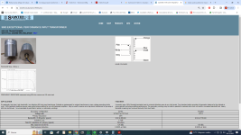
https://www.sowter.co.uk/specs/9063.php
Sowter says "Two chamber bobbin provides full geometric balance for the ultimate in noise rejection and phase splitting performance." so the schematic is correct.
I use these transformers in my line-drivers:
"Two chamber bobbin" is what the Sowter page says.Sowter says "Two chamber bobbin provides full geometric balance for the ultimate in noise rejection and phase splitting performance."
And please DON'T use a multi-meter / DVM to measure the DC resistances of the windings - that WILL magnetize the core!
"The map is not the territory."
Yes, you are quite correct.primary is always CT
The primary signal is always across both windings, otherwise the output won't be symmetrical because each output is on a separate section.
The schematic you are referring to also does not show the sectioning... it is not a physical representation of the winding stackups.
I have been using the 9063s since 2006, and have a couple in a box at my feet which are just about to go into a new line-driver.
And yes, Happy New Year everyone. 🙂
H
Ring of two type CCS? This is my general preference as well for bipolar transistors. In general I have avoided CCS in the audio path of my own equipment. I am experimenting a little with some of the IXYs devices - SY, Doug and a couple of others think very highly of these which has my curiousity piqued.
I was thinking perhaps I had a specific preference for bias approach but I think I might be almost close to agnostic. I use cathode bias with tubes like the 6J5/6SN7/6SL7 almost exclusively, fixed (grid) bias in power stages and with DHT types in general or and some high transconductance types like the 5842. I have also employed LED bias with 5842 and D3A with choke loads or tube based gyrators. I've found the LED bias sounds good in these applications sans CCS. Using high transconductance types with LED bias in particular means that you need to pay close attention to matching and target plate current vs supply voltage (since I don't currently use CCS).
Fixed bias seems to work really well with low transconductance dhts and results in reasonably predictable Ip which generally is not the case with higher transconductance types which need to be tweaked to achieve the desired operating point.
I guess there are about as many ways to do this as there are designers. 😛
15 years is a long time ago particularly for a quote. Since I made those comments I have moved on to cascode CCS typically with depletion mode mosfets and in low voltage applications JFETs. I also use cascode bipolar CCS with LEDs as references in some headphone amplifier and discrete op-amp designs.
Rod Coleman as always remains an excellent reference on all things CCS.
Rod Coleman as always remains an excellent reference on all things CCS.

Is it good or bad ? It's
Obviously rolling off...probably sounding " analog " Can you use different LL "interstate trans " ?
Obviously rolling off...probably sounding " analog " Can you use different LL "interstate trans " ?
Which configuration for the interstage are you using? What's in the rest of the design driving the IT?
Secondary not connected? How did you measure this then?
Did you measure on the open secondaries? Unloaded?
Those xformers all need a certain terminations for best performance.
Jan
Did you measure on the open secondaries? Unloaded?
Those xformers all need a certain terminations for best performance.
Jan
Last edited:
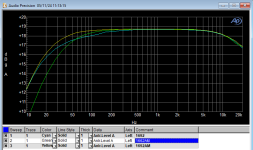
witch LL transformer??? ratio should be 1;1 ? to tune transformer a secondary load resistor its requiredI would like to share frequency response of 26 tube with LL interstage transformers
100mVrms input, about 800mVrms output, B+135V, plate current 4mA, secondary windings not connected
witch LL transformer??? Transformer model is in the comments column 1692, 1692AM and 1660AM (not 1662 - typo), all 10mA dc rated
Secondary not connected? How did you measure this then? These measurements were done on the first anode
Which configuration for the interstage are you using? that is recommended by Lundahl, Alt Q SE Line Output, will check later for Alt S SE to SE Interstage
The aim was to determine low cut, caused by the inductance of the primary winding. It looks that 95-100H is not enough
Last edited:
ALT Q is better choice (10Hz...55kHz) ... if you have low (below 2k) impedance tube (in this case inductance is only 95H).Alt Q SE Line Output, will check later for Alt S SE to SE Interstage
In this operating point #26 has 7k6 output impedance.
Using #26 with inductive load is the nightmare.
BTW Vinylsavor wrote here about this problem.
Last edited:
I ended up by designing my own xfmr for this tube (and let's say 6SN7 and alike) but it was a challenge because I wanted to be on the smallish side too, check post #5296
Last edited:
i have type 56 (2.5V grand sister of type 26)with Hammond 126C , 106H @ 10K spec but 22Kohm load
sound its fantastic ( 56 IT drive 2A3 wit SE to PP IT to drive 6BX7 CF PP to direct drive VT4C PP)
sound its fantastic ( 56 IT drive 2A3 wit SE to PP IT to drive 6BX7 CF PP to direct drive VT4C PP)
Yeah this is really the answer.Using #26 with inductive load is the nightmare.
Thomas was just concerned about the output impedance which he wanted to be 300R rather than 600R to drive a TVC. But yes, tubes like 26, 27, 37, 56, 76 need the right load. I use a resistor but it needs to be at least 39K or more if possible. I remember using a 135H plate choke with the 26. Can't remember any special problems but can't remember what it was like either.ALT Q is better choice (10Hz...55kHz) ... if you have low (below 2k) impedance tube (in this case inductance is only 95H).
In this operating point #26 has 7k6 output impedance.
Using #26 with inductive load is the nightmare. BTW Vinylsavor wrote here about this problem.
Can you please explain distortion rise above 8khz?I ended up by designing my own xfmr ... check post #5296
- Home
- Amplifiers
- Tubes / Valves
- #26 pre amp