@euro21 - looks good. How hot do your heatsinks get? I'm not looking for too much H2, just more than H3. Do you think the 26 is a better tube for a bit more H2?
The heatsink only lukewarm after few hour operation, with 18W dissipation per each side.
These DHT tubes are very linear (mainly if swing isn't too large) devices, so H2 always greater than H3.
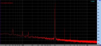
#26 also has very low THD if swing is low (H2 more than 80dB, H3 more than 91 -near 100- dB lesser than carrier signal).

If you want -more prominent- H2, try 01a with forced loading.
See here.
This is pretty similar to the Danville unit I have. It currently has AKM AK4493S DACs, but Danville now offers an upgrade to AK4499EX DACs. I haven't decided whether I'm going to use the DSP Nexus in my system yet. If I decide to go that direction, I will probably do the upgrade. The Danville has SPDIF and USB digital inputs as well as a balanced analog input.I have the Danley SC-48 FIR which is a rebadged Linea Research ASC-48 speaker management system. These support Dante (I don't have the modules), AES and balanced analog I/0. It uses AKM ADC and DACs although I don't know exactly which ones, sounds very good. I use AES in and analog out.. Two input channels on AES, and eight analog outputs on XLR.
@euro21 - thanks for the input. I am leaning toward using the 801A at this point. I like the fact that Elrog is producing them and based on what I've read, these seem quite good (although pricey).
I don't have any experience with choke input power supplies, so I could use some guidance. I'm planning to use a 6AX4 bridge (as suggested by Thomas Mayer). I've read some recommendations to use a smaller choke and first cap, followed by a large choke and second cap, as well as the opposite (starting with larger choke and cap).
I was thinking I'd use a 12H choke with a 200uF poly cap, and then split into two separate paths for the two channels with a smaller choke (e.g. 5H) for each channel. Then a smaller cap (like 22uF) for each channel located in the preamp chassis feeding a SSHV2 for each channel. If I want to allow up to 25mA anode current, I'm assuming I'll need 45mA into each SSHV2, so a total of 90mA from the main supply. Modelling with PSUD2, this seems to result in a little more than a mV of ripple into the SSHV2.
I assume I'll need a bleeder resistor in parallel with the first cap to ensure minimum current through the first choke (and to make sure it doesn't hold a long-term charge). Approximately how much current needs to flow through this bleeder?
How oversized do the chokes need to be to avoid mechanical noise? I'm planning a potted choke for the first one. PSUD2 indicates a peak current of about 115mA after the initial startup. But during the first couple hundred milliseconds, this choke sees a peak of 1A. But I don't think PSUD2 models the rectifier tube start-up. I'm also planning to use a soft-start circuit before the power transformer, so current should ramp up more slowly than is being modeled. Do I need to worry about this peak startup current? Would a choke rated at 200mA be sufficient?
Thanks for your help.
First of all, if you use SSHV2, there is no point in using complicated filtering before it.
This type regulator has input CCS and shunt device, the PSRR very high.
Because the load current of PSU is steady (due to the CCS in SSHV2), no dynamic behaviour, no difference between type of filtering (choke or capacitor input, one or more C-L, L-C or Pi part) if output hum is the same.
BTW my gyrator loaded 801 preamp has 63dB PSRR at 100Hz. Absolutely unnecessary to use any regulated PSU, simple c-L-C-L-C (I found these devices in the drawer) produces few mV hum on the common B+. It was more than enough.
@euro21 - thanks for your reply. I hear you. But I'm thinking that I might use this supply for other line stages and would like the option to experiment with just passive filtering. I'd also like to use this project as an opportunity to learn about choke input supplies. I agree it is overkill for my initial project.
@Jaytor - LC filtering makes the power xfmr more efficient, less stressed and, as a bonus, provides some sort of voltage regulation (check the old literature). The ripple resulted will be sinusoidal, which I appreciate in particular. I'll highly recommend for audio, CL filtering being the best for Tesla coils on the other hand 🙂
Here's a simulation I made years ago with the amplitude and form of the AC current through secondary windings of power xfmr (same goes for bridge topology) ... the output is identical, DC 220V/110mA

Here's a simulation I made years ago with the amplitude and form of the AC current through secondary windings of power xfmr (same goes for bridge topology) ... the output is identical, DC 220V/110mA
Last edited:
While you’re experimenting you might consider giving battery grid bias a listen.Has anyone directly compared filament bias with cathode bias and good cathode bypass caps?
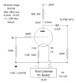
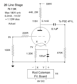
I'm on my way to doing this, with DC Link cathode bypasses. Schematics below. I'll report back when they're up and working.
Attachments
I'm curious since battery is in series with signal input, would not the type of battery used affect sound just like caps ?
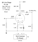
OK - so now I have the cathode bias 26 stage built and I've been auditioning it against the filament bias version. The schematics are pretty close, though not quite identical. Just small variations. Parts are very similar. New cathode bias schematic below. Listening material was opera, classical and jazz piano trio and vocals.
I can say right away that the filament bias version wins comfortably. It has greater clarity and transparency and the tonality on acoustic instruments and voices is clearly superior. Piano is notably more realistic, with more overtones and subtleties. It's a thinner overall sound than the cathode bias version with less "warmth" - it's pretty neutral in tone.
The cathode bias version seemed a tiny bit louder, though I didn't measure this. The sound was warmer with more lower mid bias. But even though the bypass caps were good DC Link Kemets, the sound lost transparency. The clarity and transparency of the filament bias version were unfortunately replaced by a more veiled overall sound. It was simply a "good" valve stage rather than a special one. The subtleties in voice and piano were less in evidence. It was consequently less involving and attention tended to wander. A disappointing result - the differences were bigger than I expected.
The conclusion is pretty simple - if you're building a 26 stage, build it in filament bias. Nothing new there, but now I have heard a direct A-B test I know the differences at first hand. I'm going to convert the cathode bias version back to filament bias. Not tried battery bias or other kinds of bias.


What LL1660 gap are you using Andy?Here's an example of filament bias with a 10Y. The cathode resistors will get very hot and I mount them above the chassis, same with the heatsink.
View attachment 1375176
I agree with Bela but only depending the configuration:First of all, if you use SSHV2, there is no point in using complicated filtering before it.
This type regulator has input CCS and shunt device, the PSRR very high.
Because the load current of PSU is steady (due to the CCS in SSHV2), no dynamic behaviour, no difference between type of filtering (choke or capacitor input, one or more C-L, L-C or Pi part) if output hum is the same.
BTW my gyrator loaded 801 preamp has 63dB PSRR at 100Hz. Absolutely unnecessary to use any regulated PSU, simple c-L-C-L-C (I found these devices in the drawer) produces few mV hum on the common B+. It was more than enough.
-I used choke input and CLC before but sounds far better CRC but I'm using Black Gates as capacitor for PSU (BG papers advice not using chokes togheter the BG at PSU), always same result using or not SSHV2 + resistor as anode load, Gyrator or cascode CCS. So I'm using CRC + Gyrator for 801A preamp also.
-If not using BG as PSU caps is other history and sounded far better input choke L-C-R-C (more dynamic and fast) than CLC and the worst CRC. Caps used 47uF 450V Nippon Chemi-Con KXG & 220uF 450V Nichicon VY both 105º C, attached caps datasheets.
Other curious things using DHT:
-SSHV2 only sounds good when loading resistors as anode load, not sounded good combined with Gyrator or cascode CCS as anode load. I need to check again with choke or line output transformer but when used SSHV2 + LL1660 10mA for 26 (used as line outpu and also as choke) the sound not was very good but not terrible bad at all.
Attachments
Last edited:
I assume your question is directed at me. No, I have not compared them myself. I was suggesting that Andy include battery grid bias in his comparison since he is currently experimenting with other bias methods using the 26.I only listened with filament bias resistor, have you compared vs batttery grid bias?
It would be interesting to hear his impressions. Very easy to give it a try.
Not sure where I saw it but there is some technically oriented builder who found that battery bias resulted in lower distortion than the other methods they tested.
OK - so now I have the cathode bias 26 stage built and I've been auditioning it against the filament bias version. The schematics are pretty close, though not quite identical. Just small variations. Parts are very similar. New cathode bias schematic below. Listening material was opera, classical and jazz piano trio and vocals.
I can say right away that the filament bias version wins comfortably. It has greater clarity and transparency and the tonality on acoustic instruments and voices is clearly superior. Piano is notably more realistic, with more overtones and subtleties. It's a thinner overall sound than the cathode bias version with less "warmth" - it's pretty neutral in tone.
The cathode bias version seemed a tiny bit louder, though I didn't measure this. The sound was warmer with more lower mid bias. But even though the bypass caps were good DC Link Kemets, the sound lost transparency. The clarity and transparency of the filament bias version were unfortunately replaced by a more veiled overall sound. It was simply a "good" valve stage rather than a special one. The subtleties in voice and piano were less in evidence. It was consequently less involving and attention tended to wander. A disappointing result - the differences were bigger than I expected.
The conclusion is pretty simple - if you're building a 26 stage, build it in filament bias. Nothing new there, but now I have heard a direct A-B test I know the differences at first hand. I'm going to convert the cathode bias version back to filament bias. Not tried battery bias or other kinds of bias.
View attachment 1439121View attachment 1439122
Andy 59uF are enough to bypass the cathode resistor for 20Hz so surely sounds more clear like using 105uF.
I'm not using LL1660. This is the driver stage for my PSE 4P1L outputs.What LL1660 gap are you using Andy?
For the Cathode bypass cap, I don't think changing the value would have too much difference. The overall difference compared to filament bias was substantial. Anyway, I've almost converted the stage to filament bias using a 10R resistor - see if that makes a difference.
I think I tried battery bias in the past - I don't remember it being better than filament bias otherwise I would have pursued it. Anyway, I have a horror of batteries. I like to have a no-maintenance amp - build it and it's done. That's just me!
Last edited:
I'm sorry Andy I mixed things, I'm asking about your 10Y schematics at posts 5.460 & 5.470 using LL1660 for 15mA.
I understand your concerns but, when used in the grid, battery life is the shelf life of the battery. In the case of a lithium that's probably 9 or 10 years. Not zero maintenance but certainly minimal.Anyway, I have a horror of batteries. I like to have a no-maintenance amp - build it and it's done. That's just me!
Just thought you might want to listen to battery grid bias since you're in experimentation mode. Especially if you're not really sure if you've tried it before or not. It's also possible you tried it in the cathode of an indirectly heated tube which is a totally different situation.
- Home
- Amplifiers
- Tubes / Valves
- #26 pre amp


