Hi euro 21,
I put 500k resistor for gridleak but sometnig is not ok,becouse on left chanel when I put gridleak in the signal is going away and this chanel is silent so no music come thru,when I unplug this gridleak the music in left chanel is again there.Hm....this is strange
I put 500k resistor for gridleak but sometnig is not ok,becouse on left chanel when I put gridleak in the signal is going away and this chanel is silent so no music come thru,when I unplug this gridleak the music in left chanel is again there.Hm....this is strange
Hi Rod,I put now 100uf mkp cap across diode strip and the hum is almost gone,just a litle bit of hum is now there.So what could be wrong??
Please sketch your input signal wiring (both channel) : RCA-pot-wiring to preamp tube, and grounding.
Is your inputs (RCA?) are independents, grounding is not common?
Is hum present when inputs are shorted?
Is your inputs (RCA?) are independents, grounding is not common?
Is hum present when inputs are shorted?
Last edited:
Hi euro21,
Yes I have RCA input,so input hot wire from rca to input o the pot and cold wire from the rca to pot ground and than from pot ground to signal ground,pot output to 1 Kohm gridstopper.On signal ground I have conected the input ground from pot,output ground for rca,Sic diode string and last psu capacitor and than from this signal ground goes wire to star ground this is for one chanel but bouth have the same wiring.
Yes I have RCA input,so input hot wire from rca to input o the pot and cold wire from the rca to pot ground and than from pot ground to signal ground,pot output to 1 Kohm gridstopper.On signal ground I have conected the input ground from pot,output ground for rca,Sic diode string and last psu capacitor and than from this signal ground goes wire to star ground this is for one chanel but bouth have the same wiring.
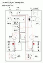
Oh yes,my preamp enclosure is from wood so the rca have no contact to enclosure to made some groundloop.
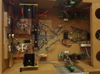
The picture of inside would be better.
As you can see my #26 preamp also has wood frame.
Each input RCA hot and cold switched by input selector, then go to #26 (to grid leak resistor neutral -local ground- point and to the grid stopper).
From #26 local ground point black wire go to global ground "bus".
This is the common point of heater bias resistor, R. C regulator, TVC input, TVC output and output RCA, HT neutral point.
Each channel is independent, no common ground (only at the PSU box -via umbilical-).
Attachments

Nice work euro21,I have put now for quick test instead the sic diode again the resistor with cap and there is only litle bit of hum but I think this vome from tubes becose it is 50hz,but you can hear this only if you go to the speaker and put your ear clise to speaker.Than I put now again the diodes inside and the 120hz hum is there and it is loud.Can it be that some diode is defective???I have mesured the voltage around this 10 diode string and it is 8.05V on bouth chanel.I dont think it some problem in grounding now,becouse with fix bias with battery it is totaly silent the preamp and with resistor/cap bias also almost totaly silent.So why this diodes make this 120hz hum noise??🤔
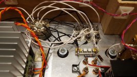
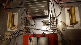
This is my prototyp 26 pre for now.now I have my gyrator inside made point to point on bartola schematic,i have made this pre in two box option,first box that you see is preamp box with filter caps,chokes and coleman regs,in second box I have only two transformer and first stage raw psu from Rod Coleman.The star point is in preamp enclosure.I must say I choose this option becouse with battery grid bias I have no hum and no hiss.
Attachments
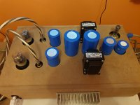
Two independent raw supplies, with independent AC coils?and first stage raw psu from Rod Coleman.
Off topic
Hi Andy,
The 5534 is quite a nice Op Amp, usually much better than the favorite-chip-du-jour.
If your input impedance is reasonably low, the AD797 can be just a tad better, but needs a little extra decoupling. Not hard to do.
If you want to get really crazy (in a good way) try Jensen 990 Op Amps. John Hardy still makes them. Expensive, but a good step beyond the normal amps on a chip (and very nice looking.) Input impedance comment applies to the 990, as well.
Regards,
John
I've been using a 5x opamp stage in front of the 4P1L, and getting good results with OPA134s and NE5534s.
Hi Andy,
The 5534 is quite a nice Op Amp, usually much better than the favorite-chip-du-jour.
If your input impedance is reasonably low, the AD797 can be just a tad better, but needs a little extra decoupling. Not hard to do.
If you want to get really crazy (in a good way) try Jensen 990 Op Amps. John Hardy still makes them. Expensive, but a good step beyond the normal amps on a chip (and very nice looking.) Input impedance comment applies to the 990, as well.
Regards,
John
Hi euro21,
Yes i have two pairs of coleman raw psu but the first is in transformer box with transformer 6V-0 and 6V-0 so two secondary this goes into raw supply left chanel and right chanel than when it comes thru shilded 1,5meter cable into the preamp box there is another pcb raw bord one for R and one for L chanel but build only with capacitors/resistor and led diode so without the rectiefer,this is only there for second filter stage.I have this at home so I used this.
Yes i have two pairs of coleman raw psu but the first is in transformer box with transformer 6V-0 and 6V-0 so two secondary this goes into raw supply left chanel and right chanel than when it comes thru shilded 1,5meter cable into the preamp box there is another pcb raw bord one for R and one for L chanel but build only with capacitors/resistor and led diode so without the rectiefer,this is only there for second filter stage.I have this at home so I used this.
So Rod and Ale,first schematic is with no hum and hiss,second with Sic diodes with hum 120hz but no hiss.I must buy some good resistor that can handle some wattage and I will try filament bias in the future also.But for now I would try this Sic option.Ale plese be so nice and tell me how you made grounding in your oreamps.You mentioned some 3 point grounds like input stage,filament return and output stage.To have this 3 points separate that hum is not come in the output stage from filament how you make this ground scheme??
Forgot to ask you. Do you have a gate stopper on the lower FET of the gyrator/mu-follower? What FET are u using?
Hi Ale,Im using 2sk170bl and yes I have 330 ohm gate stopper for this.I have yours original boards also and I have try this also but the same problem.Your boards are build original with bsk111 and also gate stopper 330 ohm.I will try today after work to go to my friend and take some mesurments with scope.It is truly strange becose with bias resistor/cap option and with battery grid bias,the pre is almost totaly silent just little bit of some 50 hz hum is there but you must put your ear totaly close to speaker to hear this.
It is truly strange becose with bias resistor/cap option and with battery grid bias,the pre is almost totaly silent ....
You simply changed R//C with SiC string? No other changing?
Hi euro21,yes several times.With resistor/cap bias verry little hum almost no hum with diode szring loud 120hz hum.
Ale plese be so nice and tell me how you made grounding in your oreamps.You mentioned some 3 point grounds like input stage,filament return and output stage.To have this 3 points separate that hum is not come in the output stage from filament how you make this ground scheme??
Hi Ale,
I would be interested in seeing your grounding scheme expanded on, as well.
I have tried a number of different grounding schemes, including 3 separate star points as suggested on your blog.
So far the schemes that gave me the lowest noise are strict star grounding (with everything getting its own flying lead to ground) and a ground bus, paying attention to where the grounds attach-- filament and PS on one end, and signal on the other, in order of sensitivity.
Best regards,
John
So today I have put this sic diode string in my another 27 triode preamp on cathode instead of resistor capacitor bias and it works without problems.Ofcourse 27 is Idht triode and I use LT1084 diy regs for filament heating.So now I think that it must be something between Rod regs and this diodes that is not ok,becose I used the same gyrator boards in the 27 like I use in my 26 pre.Hm Im truly mixed up what there could be wrong.Why all others bias options works only the diode string not??
If the capacitor across the diodes stops the hum, then I think it is electromagnetic pickup. And since the diodes are quite low impedance, it is probably magnetic field.
Components in the cathode carry the grid signal-current, as well as the cathode current. for this reason, the conductor area between:
- grid signal→socket→cathode components→ground→grid-Leak-Resistor→Grid signal input
- must be made as small as possible, or pickup will become real.
The diodes must be stacked closely together, and connecting wires must be formed to make a short loop. The grid leak resistor must be connected to this same ground-point.
Do you have a photo of the diode-string construction?
- Home
- Amplifiers
- Tubes / Valves
- #26 pre amp