chiming in late and maybe not seeing everything........ if using fast PSU, independent ones for main and biasing
one of solutions is - biasing PSU directly powered by mains switch, also powering adequate relay (with or without simple RC delay cell) and that relay powering main switching PSU
that way biasing mech. made strictly safe for SIT, and arrangement ensuring that main rail is powered only if biasing voltage is present

with or without simple RC delay cell
as best solution, ensuring loong On delay and fast Off - using any variation of Papa's, with 2 mosfets or bjt+mosfet relay circuits
posted somewhere in his latest simple amps threads
ZM,
Existing SIT amp has independent bias and main power supplies which are independently switched. Bias is powered by main switch at IEC inlet socket, main PS is switched after this through soft start module. So main PS can't come on until bias is running. Its worked to date and I'll probably use the same setup in new amp.
Thanks for your comments.
Using two 20V zeners and the existing 18V one, bias started instantly (no V-). I then connected V- (37.5V) and powered up at maximum bias. All OK, 0V across choke, Vds = 37.5. Trimmer was then slowly turned clockwise in stages to get 2.5V across the choke (Iq = 2.5A). At this point, Vds = 34.91V, Vg = -38.4. I powered down and restarted a few minutes later at the same Iq, no problems. This was repeated some time later with the same result. I connected the amp input to the output of a DAC/preamp, hooked up some headphones and listened to a bit of music. Only one channel at present but it seems to have a similar sound to the V+ version, which isn't surprising. Also, its dead quiet. In due course I'll build both channels into the existing V+ version chassis.
Ben, my knowledge of solving problems with even simple designs such as this is clearly very limited. I would not have sorted this without the knowledge, time and patience you provided. This is greatly appreciated. It might also be useful for others who may be considering using SMPS's with this or similar designs.
Great news! I had not explored the use of SMPS so I did not anticipate the possible issues. But with you as an unofficial smps beta tester and with an assist from pinholer regarding D3, it seems that we now have a solution.
I have revised the schematic for the independent bias supply version to reflect the D3 voltage. The PCB alterations are shown in post #779: PCB Alterations for Independent Bias Voltage Supply
So if a SMPS is used for the V- supply, it is best to have an independent bias voltage supply. With a linear power supply, the original design with the lower voltage bias supply in series with the main power supply is still the simplest way. My amplifier was built that way and I have had no problems with it.
So if a SMPS is used for the V- supply, it is best to have an independent bias voltage supply. With a linear power supply, the original design with the lower voltage bias supply in series with the main power supply is still the simplest way. My amplifier was built that way and I have had no problems with it.
Attachments
Ben, could 2sk60 vfet be used in this amp. I realise that the power would be much lower, but those vfets have a nice sound. I am using all smps supplies,thanks.
Yes. Use a power supply of 19V and set the current at 1.3A. For the lower current, a Hammond 159ZC may be used in place of the 193V.
With the smps for 19V, it is best to use a modified bias supply. The pcb needs to be modified as shown in post #779. However, the bias supply voltage can also be lowered. A 30V smps can be used for the bias supply. With a smps bias supply, the 3 pin voltage regulator is omitted and a wire jumper placed between pins 2 and 3 (Vout and Vin) of the voltage regulator location on the pcb, and D1, D2, R1, R2, C1A, and C4 are also omitted.
.#779 - PCB mod for SMPS
With lower voltages, capacitor voltages may be lowered.
Modified circuit for 2SK60:
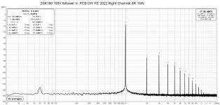
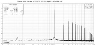
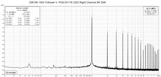
I am now using the DIY FE 2022 as my preamp for a while now, and I find the lower distortion better sounding. As I have mentioned before when I changed from common source to common drain, the reduction in distortion resulted in additional clarity in the high frequencies and a more realistic sound. The DIY FE 2022 has lower distortion than the 2SK79 preamp that I was using previously, and the preamp switch resulted in further similar change in sound.
I had done these these FFTs of the DIY FE 2022 with the 2SK180 choke loaded follower amp quite a while ago and I forgot to post them.
For comparison the FFTs of the 2SK79 preamp with the 2SK180 follower amp are here: 2SK79 Preamp and 2SK180 Choke Loaded Follower Amplifier
Left Channel:
I had done these these FFTs of the DIY FE 2022 with the 2SK180 choke loaded follower amp quite a while ago and I forgot to post them.
For comparison the FFTs of the 2SK79 preamp with the 2SK180 follower amp are here: 2SK79 Preamp and 2SK180 Choke Loaded Follower Amplifier
Left Channel:
Attachments
-
 2SK180 193V Follower V- Left Channel DIY FE 2022 8R 1W.jpg239.2 KB · Views: 145
 -
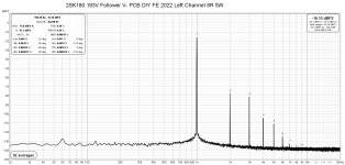 2SK180 193V Follower V- Left Channel DIY FE 2022 8R 5W.jpg240.6 KB · Views: 152
 -
 2SK180 193V Follower V- Left Channel DIY FE 2022 8R 10W.jpg239.9 KB · Views: 127
 -
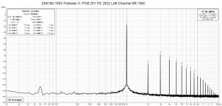 2SK180 193V Follower V- Left Channel DIY FE 2022 8R 15W.jpg241.4 KB · Views: 129
 -
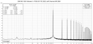 2SK180 193V Follower V- Left Channel DIY FE 2022 8R 20W.jpg242.5 KB · Views: 127
 -
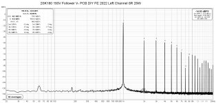 2SK180 193V Follower V- Left Channel DIY FE 2022 8R 25W.jpg243.5 KB · Views: 137
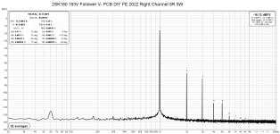
Right Channel:
Attachments
-
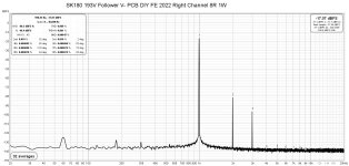 2SK180 193V Follower V- Right Channel DIY FE 2022 8R 1W.jpg241 KB · Views: 107
 -
 2SK180 193V Follower V- Right Channel DIY FE 2022 8R 5W.jpg241.4 KB · Views: 118
 -
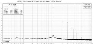 2SK180 193V Follower V- Right Channel DIY FE 2022 8R 10W.jpg241.3 KB · Views: 110
 -
 2SK180 193V Follower V- Right Channel DIY FE 2022 8R 15W.jpg240.6 KB · Views: 109
 -
 2SK180 193V Follower V- Right Channel DIY FE 2022 8R 20W.jpg242.8 KB · Views: 118
 -
 2SK180 193V Follower V- Right Channel DIY FE 2022 8R 25W.jpg243.9 KB · Views: 118
Solid work Ben. I think that this is a classic case of less is more. These SIT devices have enough distortion (even in common drain) and at your operating point it’s better if the front end is cleaner.
Very cool 😎
Very cool 😎
Yes, the DIY FE 2022 is a great voltage gain front end for SIT amplifiers, and in my opinion common drain is the way to go with SITs. It is great with all music.
I have come to appreciate lower levels of distortion, but the most important thing is to still have second order harmonic dominate. And also to have enough power so that the amplifier stays at low power output and low distortion level during listening.
I have come to appreciate lower levels of distortion, but the most important thing is to still have second order harmonic dominate. And also to have enough power so that the amplifier stays at low power output and low distortion level during listening.
@Ben Mah, I was pleasure meeting you at the Burning Amp festival and also thank you for giving me two Rev. 1 boards of the amplifier. I got the SIT THF-51S from ebay and have spent some time on digikey to get the needed parts, would you (or anyone else for that matter) mind having a quick look at the part list let me know if you have any comments? My main difficulties in finding the parts were:
Any comments are appreciated. Next step is to start planning the power supply.
- D3: zener diode it's a TZX18B instead of a BZX18B
- D4: LED is a 5V yellow
- R5: resistor is 34.8k as I could not find a 35k one
- U1: is a LM317 1.5A, is that correct?
Any comments are appreciated. Next step is to start planning the power supply.
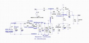
| Hammond 193V (150mh,@3A DC) | L1 | HM1567-ND |
| CAP ALUM 1000UF 20% 25V RADIAL | C1 | 493-10989-1-ND |
| MKP 4F 10% 350VAC PITCH 27,5 | C2, C5 | 2870-MKP1847C540355K2-ND |
| CAP ALUM 33UF 20% 25V RADIAL | C3 | 493-15435-ND |
| CAP ALUM 47UF 20% 25V RADIAL | C4 | 493-3179-ND |
| CAP ALUM 10000UF 20% 50V SNAP | C6 | 493-13364-ND |
| CAP ALUM 1000UF 20% 50V SNAP | C7 | 493-16228-ND |
| CAP ALUM 470UF 20% 63V RADIAL | C8 | 493-11032-1-ND |
| DIODE GEN PURP 100V 1A DO41 | D1,D2 | 1N4002DICT-ND |
| PTZ18B: DIODE ZENER 18V 500MW DO35 | D3 | TZX18B-TAP |
| Yellow 585nm LED Indication - Discrete 5V Radial | D4 | 516-1341-ND |
| RES 240 OHM 1/4W 1% AXIAL | R1 | RN60D2400FB14 |
| RES 2.0K OHM 1/4W 0.1% AXIAL | R2 | CMF502K0000BEEB |
| RES 10.0K OHM 1/4W 1% AXIAL | R3 | CMF5010K000FHEB |
| RES 47K OHM 1/4W 1% AXIAL | R4 | RN60D4702FRE6 |
| 35k:RES 34.8K OHM 1/2W 1% AXIAL | R5 | CMF5534K800FHEB |
| RES 1.50K OHM 1/4W 1% AXIAL | R6 | CMF501K5000FHEB |
| RES 5K OHM 1/4W 1% AXIAL | R7, R8 | RN60D5001FB14 |
| RES 220 OHM 1/4W .1% AXIAL | R9 | RN60C2200BB14 |
| RES 22 OHM 1/4W 1% AXIAL | R10 | RN60C22R0FB14 |
| TRIMMER 20K OHM 0.5W PC PIN TOP | RV1 | T93YA203KT20 |
| Linear Voltage Regulator IC Positive Adjustable 1 Output 1.5A TO-220-3 | U1 | LM317HVT/NOPB-ND |
It was a pleasure meeting you too. BAF was great.
-D3 zener TZX18B is ok.
-D4 LED is just for visual indication of power. It can be any colour of your choice.
-R5 34.8k is ok. It is not critical.
-LM317 1.5A is ok. Actual current is in the mA range.
-Yes, 1/4W resistors, except R9, 220R, make that 3W (what Botte said).
-D3 zener TZX18B is ok.
-D4 LED is just for visual indication of power. It can be any colour of your choice.
-R5 34.8k is ok. It is not critical.
-LM317 1.5A is ok. Actual current is in the mA range.
-Yes, 1/4W resistors, except R9, 220R, make that 3W (what Botte said).
@Ben Mah and @Botte thank you very much!
I have now created the parts list for the power supply. I have some more questions:
I have now created the parts list for the power supply. I have some more questions:
- For C5 & C6 are ceramic capacitors 1000V OK?
- LED D5 is again just an indicator, correct? Any LED works with any forward voltage?
| CAP ALUM 22000UF 20% 50V SNAP | C1,C2,C3,C4 | 338-1599-ND |
| CAP CER 10000PF 1KV Z5U RADIAL | C5 | 1255PH-ND |
| CAP CER 0.015UF 1KV Z5U RADIAL | C6 | 562R5GAS15-ND |
| BRIDGE RECT 1000V 35A | Bridge Rectifier | 4878-KBPC3510FP-ND |
| FIXED IND 10MH 5A 160 MOHM CHASS | L1 | HM1555-ND |
| RES 4.0K OHM 3W 1% WW AXIAL | R1 | RSB-4.0KRCT-ND |
| RES 40K OHM 0.1% 1/4W AXIAL | R2 | 273-MOX70034002BYE-ND |
| RES 33 OHM 3W 1% WW AXIAL | R3 | RSB-33CT-ND |
| LED RED DIFFUSED T-1 3/4 T/H | D5 | 160-1969-ND |
Are you building monoblocks, with one power supply per monoblock? I built my amps as monoblocks.
C5 and C6 for the snubber - Mark Johnson recommended metallized film, EPCOS B32529.
Yes, LED is an indicator so your choice of LED, and it is not critical. The resistor is not critical either, so there is no need for an expensive resistor.
You will also need a bridge rectifier for the additional bias voltage supply. That would use the 15VAC secondary winding on the Antek transformer. The output from the bridge rectifier would go to the amplifier board.
Are you planning to use PS board that I designed? Do you need the Gerber files?
Thanks for the clarifications. I will add a second rectifier to my shopping cart. Yes, I plan to make mono-blocks.
Could you send me the gerber files, i'll oder them from jlcpcb (or another service that you can recommend). I can't privately message you my email since my messages are moderated. Can you message me first so I can reply?
Could you send me the gerber files, i'll oder them from jlcpcb (or another service that you can recommend). I can't privately message you my email since my messages are moderated. Can you message me first so I can reply?
- Home
- Amplifiers
- Pass Labs
- 25W Single Ended Hammond 193V Choke Loaded 2SK180 L'Amp