I don't have a scale so I cannot weigh my monoblocks.
Based on the weight of the chokes and power transformer and PS capacitors, and a guesstimate of the weight of circuit boards and parts, I would estimate the weight to be approximately 25 pounds excluding chassis and heat sink.
Assuming a conservative estimate of monoblock chassis and heatsink at 20 pounds, the total estimated weight is 45 pounds. I think that may be on the high side.
193V 9 lb
159ZJ 3 lb
Power transformer 7 lb
PS capacitors 1 lb
PS board, amplifier board and parts, miscellaneous parts 5 lb (a guesstimate)
chassis and heatsink 20 lb (a guesstimate)

I am modelling the 2SK180 and 2SK182 in paraphase mode with a choke load, in the source. It looks rather good (such as only about a -1dB loss going from 8ohm to 4ohm).
The frequency is good too. As well as the distortion.
BUT:
The output needs to be inversed ("earth" is at the plus side), because there the power supply is. But when I do a plot of the Vplus, it is very high in low frequencies, This is confusing for me. I am not ready yet to test,
And with source load, it is 22 dB at 10Hz and 65 db at 100Hz. (blue/auqua)

The resistor in the source is properly decoupled.


The frequency is good too. As well as the distortion.
BUT:
The output needs to be inversed ("earth" is at the plus side), because there the power supply is. But when I do a plot of the Vplus, it is very high in low frequencies, This is confusing for me. I am not ready yet to test,
- but the question remains, what is happening? What am I modelling wrong. Or is this just a no-go land? (Western Electric did it with tubes . . .)
And with source load, it is 22 dB at 10Hz and 65 db at 100Hz. (blue/auqua)
The resistor in the source is properly decoupled.
I had never heard of paraphase before so I did an internet search and I came up with a phase inverter/splitter for push-pull.
However, I simulated your circuit (only the source loaded circuit) and I got similar results. I say similar because the decreasing frequency response in my model was at a point between the speaker and capacitor.
After some thought, I believe that the speaker impedance in conjunction with the output capacitor form a low pass filter, with the input at the source side of the speaker and the output at the other side of the speaker, resulting in a drop in low frequency output from the speaker. Anyway, that's my theory, and I've been wrong before. 🤓
As nicoch58 said, with DC blocking, no air gap output transformer needed. I suppose a single ended solid state circuit with an output coupling cap is similar to parafeed in that it has an output cap, but because of the lower output impedance of the transistor, no output transformer for impedance matching is required. So without an output transformer is it still parafeed?
I have built SE tube parafeed amps, with output transformer primary/parafeed cap connected to either tube cathode or ground.
My understanding is that connecting the transformer primary/parafeed cap to the tube cathode instead of ground is called Ultrapath.
The attached sim file is missing the SIT symbol, so it will not run. You should run it again and check and compare to what I found.
Edit: I did some internet searching the connection of the transformer primary/parafeed cap is not Ultrapath. Ultrapath is the addition of a capacitor between power supply and cathode.
Last edited:
Yes the SIT symbol/model, gave me trouble too.
Here are my ASY symbols: hope this helps. Maybe it would be possible to change the arrow such that it looks more like a SIT symbol instead of a Mosfet symbol. But that is for others to try . . .
Here are my ASY symbols: hope this helps. Maybe it would be possible to change the arrow such that it looks more like a SIT symbol instead of a Mosfet symbol. But that is for others to try . . .
Attachments
Last edited:
I was lazy so I used my own SIT symbol and ran one of the circuits.
I also played with my circuit with your values. After comparing and changing various values, I found that the factor that affected the frequency response of the AC in the power supply was the power supply series resistance. Lower resistance, higher attenuation. But if the power supply is clean, then there is no noise to attenuate.
In my simulation I did not input a power supply series resistance so the attenuation was constant throughout the frequency range.
I have made some progress today on the right channel 🥳 (i forgot to put the 2nd rectifier in the picture):

@Ben Mah would you mind having a quick look at my schematic below of how to wire things together and let me know if I got it right?

In particular my questions are:
Adrian
@Ben Mah would you mind having a quick look at my schematic below of how to wire things together and let me know if I got it right?
In particular my questions are:
- Is the V- power supply correctly connected with "Right Channel" PCB?
- Is the jumper set correctly?
- Are the 29R snubber resistors used for both 30V and 15V? Do you have a part number (e.g. Digikey)?
- Do you use the FE 2022 as a pre-amp or front end? In case you use it as a front end, what gain are you using?
- What are you using to electrically isolate the 2SK180 from the chassis?
Adrian
Hi Adrian,
It's been a while since BAF2023. It's great to see that you are making progress. You should be finished by BAF2024.🙂
1. Yes, V- is power and V+ is ground.
2. Yes, it is a V- power supply so the inductor is in the V- side and the V+ (ground) side is jumpered.
2a. Because it is a V- power supply the CL60 ground lift should be on the V+ side as it is ground, but it should be located at the output of the power supply, not at the input. So move the CL60 to V+ out.
3. The snubber resistors are dependent on the transformer. https://www.diyaudio.com/community/...rmer-snubber-using-quasimodo-test-jig.243100/
4. I use the DIY FE 2022 as a preamp set to the standard gain of 10.
5. This is what I used: https://www.mouser.ca/ProductDetail/567-CD-02-05-C-54 This has no holes so I punched holes to suit the 2SK180. I used this because it was convenient for me to purchase it along with other components that I ordered from Mouser. However you can use other interface products. Many use Keratherm.
One other thing to note: I used Antek transformers and I have had no problems with paralleling the secondary windings and connecting to one rectifier block. I believe the Anteks are bifilar wound so their secondaries are equal in winding and voltage. However some believe it is better to be on the safe side and have a rectifier block on each secondary and parallel the DC output. The potential issue is that the two secondary windings are not equal in length causing one winding to dominate and cause problems if the secondaries are paralleled.
Last edited:
Ok, I see. I would make sense to call it GND instead of V+, though.Because it is a V- power supply the CL60 ground lift should be on the V+ side as it is ground
Do you have a link to that 4 caps CLC psu board?I have made some progress today on the right channel 🥳 (i forgot to put the 2nd rectifier in the picture):
View attachment 1301871
Thanks
Hi Adrian,
I may have missed a few things in my previous post.
If you look at the schematic in this post (https://www.diyaudio.com/community/...-choke-loaded-2sk180-lamp.366312/post-7203653), the snubber resistors for the Antek AS-3430 were 33R for the parallel 30VAC secondaries and 29R for the a 15VAC secondary.
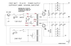
Looking at your diagram and the picture of the parts that you have, I see a power switch and IEC socket for the AC. What I do not see is a fuse holder. That is necessary. Also highly recommended is a CL60 thermistor for each transformer primary winding to work as a soft start. The wiring would be as shown in the typical First Watt power supply schematic attached. The attached schematic is for bipolar supply but the AC input portion from IEC jack to power transformer primary windings is the same for a unipolar power supply. The fuse for the Antek as-3430 would be 300VA/120V = 2.5A slow blow.
I may have missed a few things in my previous post.
If you look at the schematic in this post (https://www.diyaudio.com/community/...-choke-loaded-2sk180-lamp.366312/post-7203653), the snubber resistors for the Antek AS-3430 were 33R for the parallel 30VAC secondaries and 29R for the a 15VAC secondary.
Looking at your diagram and the picture of the parts that you have, I see a power switch and IEC socket for the AC. What I do not see is a fuse holder. That is necessary. Also highly recommended is a CL60 thermistor for each transformer primary winding to work as a soft start. The wiring would be as shown in the typical First Watt power supply schematic attached. The attached schematic is for bipolar supply but the AC input portion from IEC jack to power transformer primary windings is the same for a unipolar power supply. The fuse for the Antek as-3430 would be 300VA/120V = 2.5A slow blow.
Attachments
Thanks @Ben Mah, I'm close to assembling and testing the first monoblock amp, but I do have a few more questions:
Thanks, Adrian

- For the three thermistors per amp: is the CL-60 ICL 10 OHM 25% 5A 19.56MM (digikey) good, or what would you recommend?
- snubber network, your schematic does not have one for the 15V circuit, can you also let me know which capacitors value used? I have the same Antek transformers as you are using.
- So the FE2022 is a fixed gain (x10) preamp?
Thanks, Adrian
- Home
- Amplifiers
- Pass Labs
- 25W Single Ended Hammond 193V Choke Loaded 2SK180 L'Amp