Hi Ben, I am going to order the THF-51S's.
I would like to ask for your Gerber files.
I'll order all the other parts...
Thanks!
I would like to ask for your Gerber files.
I'll order all the other parts...
Thanks!
Gerber files sent.
I don't know how many amps you will be building but I strongly suggest that you build one and get it working before building others.
Enjoy the build.
I don't know how many amps you will be building but I strongly suggest that you build one and get it working before building others.
Enjoy the build.
THANKS for the gerber files...!
I am going to build 4 mono blocks... I'll take your advice! First make one amp work, then copy the rest.
Thanks again!
I am going to build 4 mono blocks... I'll take your advice! First make one amp work, then copy the rest.
Thanks again!
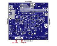
The posts for the V- power supply Follower with PCB starts here: https://www.diyaudio.com/community/...-choke-loaded-2sk180-lamp.366312/post-7195985
The schematic shows the SIT drain connected to Ground. The PCB has the connection pads labeled.
Also see this post for building tips: https://www.diyaudio.com/community/...-choke-loaded-2sk180-lamp.366312/post-7270513
The schematic shows the SIT drain connected to Ground. The PCB has the connection pads labeled.
Also see this post for building tips: https://www.diyaudio.com/community/...-choke-loaded-2sk180-lamp.366312/post-7270513
PiAir, I just want to make sure that you understand that I started out with a common source amp that had both current and voltage gain, and also higher distortion. That was changed to a common drain amp that has only current gain and lower distortion, which is what the PCB is for.
Ben, I have read all pages... Somehow your common drain amp appeals to me. I think I use the JFET BOZ preamp.

Btw, do you have a schematic for the powersupply?
Btw, do you have a schematic for the powersupply?
Power supply posts start here:
https://www.diyaudio.com/community/...-choke-loaded-2sk180-lamp.366312/post-7203653
https://www.diyaudio.com/community/...-choke-loaded-2sk180-lamp.366312/post-7203653
Swap Meet: Pair of Hammond 193V chokes for a good price (Europe only):
https://www.diyaudio.com/community/threads/hammond-193v-pair-chokes.414469/post-7721787
I do not know the member. I just saw the ad.
https://www.diyaudio.com/community/threads/hammond-193v-pair-chokes.414469/post-7721787
I do not know the member. I just saw the ad.
Some Thoughts on Amplifier Grounding
I mentioned amplifier grounding in an earlier thread, so this is my take on amplifier grounding. It has worked for me on the amplifiers and preamplifiers that I have built. I hear no noise from my 103dB sensitive speakers when my diy preamps and amps are in the system.
There are two grounds in a preamplifier or amplifier: the power supply ground and the audio ground.
A power supply converts AC power to DC power, then filters clean it up, reducing the voltage ripple to an acceptable level. A typical linear power supply that most of us use has either a CRC or CLC filter section to reduce the ripple. The ripple is the greatest at the first capacitor and much less at the last capacitor. This ripple affects the ground too, so the ground at the first capacitor is not as clean as the ground at the second capacitor. For this reason, do not tie all of the power supply filter capacitors together at one point. You do not want the dirty ground at the first capacitor to pollute the clean ground at the last capacitor. The grounds for individual capacitors should therefore be physically separated. Do not star ground the power supply capacitors.
The audio ground is the ground for the audio signal. Typically the audio signal originates at the audio board input, travels through the audio circuit, and outputs at the audio board output. In a power amplifier, the audio output is the speaker output. There is a ground associated with the audio input signal, audio signal through the audio circuit, and audio output signal There should not be any voltage difference in the audio signal ground. Voltage may be generated when there is resistance in the path of the electrons. It's Ohm's Law. For zero voltage, zero resistance is required, and since wire has resistance, then zero wire length is needed. The audio ground is where the grounds should be star connected.
In practice, zero wire length is not always possible. In my amps, I group the speaker output and speaker ground, and power supply voltage and power supply ground close together so effectively that is the star ground. The input signal and ground are usually a bit farther away due to layout and routing, but if the circuit is hard wired, I would have a heavy gauge wire directly connecting the input ground to the star ground, or if the circuit is on a PCB I have a direct low impedance path from input to star ground.
Now to the question of where to connect the speaker ground. As noted I connect the speaker ground to the audio circuit board, at the location of the power supply ground. That keeps the power supply ground and the speaker ground at exactly the same potential. Now some argue for the speaker ground to be connected to the power supply board. Assuming the power supply board is separate from the audio board, a wire would connect the power supply ground to the audio ground. This wire will have some resistance. The resistance may not be much, but it will be there. Therefore, there will be a voltage difference between the ground at the power supply board and the ground at the audio board, albeit small.
Another scenario would be if a power supply capacitor is located on the audio board at the power supply input. I would argue then that the power supply output is not at the power supply board, but at the output of the capacitor on the audio board, and that the connecting wires and onboard capacitor form the final RC filter of the power supply. The supply voltage and ground would be the cleanest at this point. So is where the power supply ground meets the audio ground.
Another reason for connecting the speaker ground to the audio board is to keep the loop area of the speaker output and ground small. That loop area can be kept small with the speaker ground connected to the power supply board, but that would entail routing the speaker out wire next to the power supply wires between the audio board and the power supply board until the speaker wire reaches the power supply board, where it then can be paired with the speaker ground wire.
Attached is a sketch illustrating what I have described. Also included are pictures of amplifier PCBs by Nelson and Zen Mod that have speaker grounds on the amplifier board.
So this is why I do what I do with my builds. Since this is diy, a builder can follow their own path, and as long as they are safe and happy, all is well.
All of this may be moot if the speakers in the system are of low sensitivity so that noise is not audible. Or if the amplifier is well built with proper attention paid to keep noise to a minimum, the small difference between grounding the speaker at the audio board or power supply board may not be audible.
Be happy, have fun diying, and enjoy the music.
Attachments


Thanks Ben. That is really good information!
I also try to figure out wich wires have to be twisted, and where best to place these.
I also try to figure out wich wires have to be twisted, and where best to place these.
Twisted Wires
All wires in a circuit should be twisted. Wires can behave as antennae, for both broadcasting and receiving. Twisting wires reduces their ability to broadcast and receive signals that can interfere with the amplifier's performance. The circuits include:
- AC power from the power input to the power transformer primary windings, including to fuse and power switch, etc.
- AC power from power transformer secondary windings to rectifier diodes/rectifier bridges
- DC power from rectifier diodes/rectifier bridges to power supply filters (capacitors, CRC/CLC filters, etc.)
- DC power between capacitors, resistors, chokes in power supply filters if they are hard wired
- DC power between power supply output and amplifier audio circuit/board
- AC input signal from amplifier input jacks to amplifier audio circuit/board
- AC output signal from amplifier audio circuit/board to speaker output jacks
AC power wires and components should be kept as far as possible away from AC signal wires and audio circuits. In a stereo amplifier, locate the AC power wires down the the centreline of the chassis, against the bottom plate. In mono block amplifier, locate the AC power wires against on side of the chassis, against the bottom plate, and locate the audio circuitry on the opposite side of the chassis. AC power input should be kept as far away as possible form audio input and speaker output jacks. Power transformers should be kept as far away as possible from audio signal wires and jacks, especially input signals and the audio input circuitry.
https://www.diyaudio.com/community/attachments/se-tokin-choke-loaded-follower-amplifier-jpg.1325443/ shows my 2SK180 choke loaded follower amplifier's twisted wires.
This video gives a good explanation and demonstration of why twisted wires are a good thing.

Ben - thanks for posting cool extra bits in this thread. They are informative, enjoyable and nicely written!
- Home
- Amplifiers
- Pass Labs
- 25W Single Ended Hammond 193V Choke Loaded 2SK180 L'Amp