The 193V is 150mH and 1.0DCR with 3.0A maximum whereas the 195T10 is 100mH and 0.42DCR and 10A maximum.
The 150mH will get you a bit more frequency range but probably not noticeable in real life listening.
If you have both you can always try both. The difference in DCR will change the operating point so you will need tweak it a bit to find one that suits your taste.
My thought is that if you are not going to go above 3.0A is to use the 193V and take advantage of the higher inductance.
even made a bias/amp pcb for it, totally unnecessary. Vds 34Vdc, Vgs -3.463, 2.5A. Definitely worthy of a chassis for sure, thanks Ben! Btw, where do you guys get the isolation mounting hardware and thermal pads? MJPA was out of thermal pads. Tough to put together a chassis with live sinks😀
Attachments

Have you listened to it?
I used these for isolation:
https://www.mouser.com/ProductDetai...gpLDsm55B6X%2Bg%2BcZ0tGtOLXguSG%2B5ksjxSCVCO5
They come with no holes so I punched holes to suit. The screws and shoulder washers came with my 2SK180 so I didn't need to purchase any.
I have nearly finished one power supply, so I am getting closer to the finish. 🙂
Yes! Just one channel though, even then its pretty amazing, enough to sit back and enjoy it. Gonna finish the other channel and put together the J113 buffer.
Thanks for the link..completely finishing these projects is the hard part
Thanks for the link..completely finishing these projects is the hard part

oh boy
take a look at SOA graphs in part datasheet, DC part
this isn't bloody elevator SIT, that's modern switchieswitchie
take a look at SOA graphs in part datasheet, DC part
this isn't bloody elevator SIT, that's modern switchieswitchie
50-60Vds and 5A are high but perhaps 28Vds and 3.2A as in the BAF2015 Schade amplifier.
Inductor load instead of mu follower/current source.
Saves on V+ and heatsink, a bit less power.
Inductor load instead of mu follower/current source.
Saves on V+ and heatsink, a bit less power.
Had a brainstorm, not my idea. Seeing as these SITs are expensive and not super plentiful, this may be a good alternative...? Thinking something like 50-60Vds@5A, watercooled of course. Thoughts...?
A note of caution with that setup:
If I remember correctly: with the normal active CCS then there is no real risk of thermal runaway since the overall current is constrained by the upper opto CCS.
With a choke as CCS the lower FET can conduct as much current as it wants with no breaks on thermal runaway. When I experimented with that setup I added a 0.235 ohm source resistor for this reason. If you want the feedback circuit to ignore the source resistor then you can move the 1000 uF cap negative to above the source resitor like the F6 does.
Last edited:
One Channel Finished
One channel is finished. I finished the power supply yesterday, tested it, and adjusted the bias.
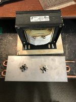
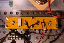
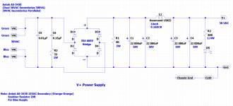
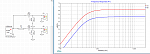
The power supply with an Antek AS-3430 (30VAC 300VA) powering a CLC filter (44mF-Hammond 159ZJ-44mF) outputted 37.5 to 38.0 VDC under load. The voltage varied because of AC line variation over the three hours or so that I had it running. So the supply voltage was more or less what I had anticipated.
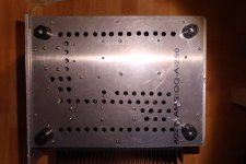
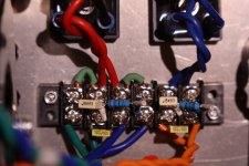
The bias stabilized after warm up as the temperature also stabilized. The interior of the case with the top in place was only a bit warm, so the holes that I drilled into the bottom plate, along with the 35mm rubber feet that provided clearance from floor to bottom plate to allow for better air flow, did their job.
So onward to finishing the other channel. Another bottom plate to drill, parts to install, and wiring to finish.
Here are some pictures and the schematic of the V+ power supply. I Quasimodoed the Antek AS-3430 and have included the snubber values.
One channel is finished. I finished the power supply yesterday, tested it, and adjusted the bias.
The power supply with an Antek AS-3430 (30VAC 300VA) powering a CLC filter (44mF-Hammond 159ZJ-44mF) outputted 37.5 to 38.0 VDC under load. The voltage varied because of AC line variation over the three hours or so that I had it running. So the supply voltage was more or less what I had anticipated.
The bias stabilized after warm up as the temperature also stabilized. The interior of the case with the top in place was only a bit warm, so the holes that I drilled into the bottom plate, along with the 35mm rubber feet that provided clearance from floor to bottom plate to allow for better air flow, did their job.
So onward to finishing the other channel. Another bottom plate to drill, parts to install, and wiring to finish.
Here are some pictures and the schematic of the V+ power supply. I Quasimodoed the Antek AS-3430 and have included the snubber values.
Attachments

Thanks everyone for your encouraging comments.🙂
ZM, my drill is handy.😀
GREAT WORK, Ben!
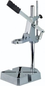
Before I had a space for my tools, I used one of this:
Attachments
Zen Mod, Thanks, but I don't understand Zenglish: Master Scavenger??
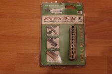
peppennino, Thanks. I hand the drill most of the holes with no problems. The only holes that I make sure that I keep them as perpendicular to the plate as possible are the holes that require tapping and holes in plates thicker than 1/8". For those I use a drill guide.
When I drill holes, I have a wood box on the floor, plate to be drilled on top of the box, one foot on the plate, and drill from above. The holes end up fairly perpendicular. When I need the drill guide, one hand (a finger or two or three) on the guide, and drill in the other hand. Usually this is for M3 and M4 size holes so not a lot of effort is required to hold the guide in place. For large holes with stepped drill bits, no guide is necessary, even in thicker plate. I have drilled front panels free hand for round on-off switches with a stepped bit with no problems.
The drill guide is handy for keeping a tap perpendicular in holes too.
The second bottom plate was drilled this afternoon so all I have left to do is wire up the power supply. Then it will be all done and I will be able to listen to the amps in stereo.🙂
Attachments
Something that was bothering me was what effect would this output impedance have on a passive crossover. I asked this question over on our Xsim Free Crossover Design thread.
AllenB in post #946 was kind enough to calculate the changes to my simple crossover assuming an 8 ohm source resistance as well showing how he arrived at the new values. Where the top schematic is assuming almost no source resistance and the lower one the same xover point but an 8 ohm source resistance.
AllenB in post #946 was kind enough to calculate the changes to my simple crossover assuming an 8 ohm source resistance as well showing how he arrived at the new values. Where the top schematic is assuming almost no source resistance and the lower one the same xover point but an 8 ohm source resistance.
Attachments
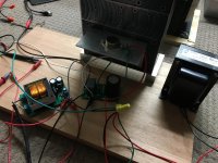
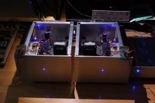
The mono blocks are finished. Biasing is done. It takes over two hours for the temperature and bias to reach a maximum. There is quite a bit of heat sinking and chassis mass to heat. The final bias varies a bit depending on the time of day, as the wall VAC varies.
The sound is typical of my SIT amps - it is excellent. I am very happy with the results. From memory, I don't believe the sound is much different from my BAF2015 THF-51S mono blocks. If I were to listen to them separately I don't think I would be able to identify which amps were playing.
I am glad I built these amps. For those of you that are bemoaning the lack of Sony VFETs, there are still many Tokins available for purchase. They may not be as cheap as they used to be, but at least they are still available. There are various amps that can be built with them, and they will sound just as good or even better than Sony VFET amps. Another plus for the Tokins is that you can build higher power amps than with Sony VFETs.
This amp is like a solid state version of a single ended 211 amp. I used to be a big fan of tubes, although I never ventured into 211/845 land. However, solid state doesn't have the problem of tube aging and tube noise, and the dangers and cost of extremely high voltage power supplies. Also the very low parts count of this amp is great - simple to build and simple to trouble shoot. It is so simple that if you double and triple check and test at various stages of the build, trouble shooting is probably not necessary. My build was trouble free.
Happily listening to music, enjoying my new amps.
🙂
Attachments


Truly inspirational!
Awesome job Ben!
(My ZenGerish dictionary suggests Zen Mod was complementing your ability to salvage the badly cut aluminum plates.)
Awesome job Ben!
(My ZenGerish dictionary suggests Zen Mod was complementing your ability to salvage the badly cut aluminum plates.)

- Home
- Amplifiers
- Pass Labs
- 25W Single Ended Hammond 193V Choke Loaded 2SK180 L'Amp