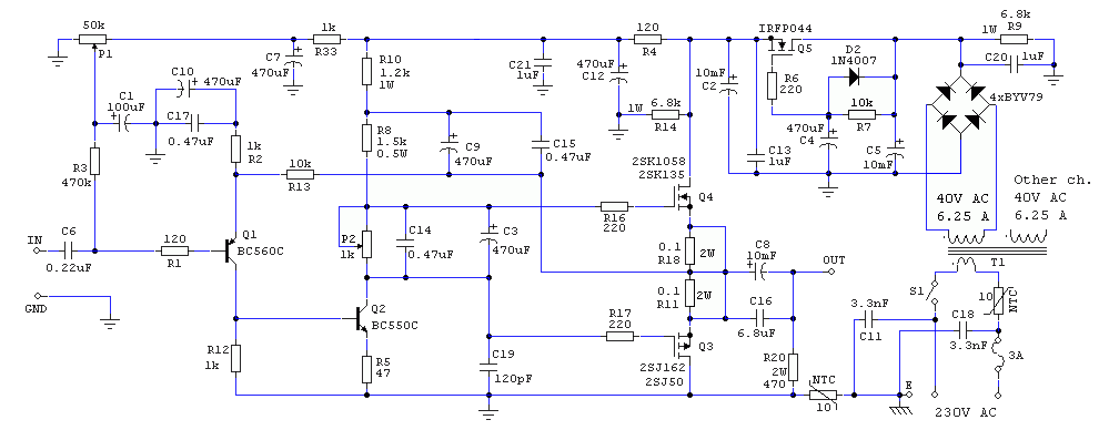
Nice Work!
p.s. Little note: gate stopper resistors should be as near to the gate as possible.
In Your version - these are as far as possible 🙁
Also low power signal "GND" shares same trace as power "GND", this practice should be avoided. It should go with separate traces to star gnd poi1nt.
I agree. This PCB was designed some year ago, and in speed. Though, I made amp with that PCBs and.. In a very serious system, with serious source, serious speakers and sound absorbers and diffusers - this amp shined like a true star... So I decided not to make new modified PCBs 😀
In a link I provided you can download Eagle PCB files and everyone is free to modify PCB as long as they want...
No, there is no BUMP (as Juma said, obviously), there is just some wait time for output cap to fill with electricity before the pop-rock starts.
If you gonna make this amp, although it work very fine with bias of 500mA, I recommend making it as specified, with 1A3 bias - it will shine even more... 🙂
p.s. Little note: gate stopper resistors should be as near to the gate as possible.
In Your version - these are as far as possible 🙁
Also low power signal "GND" shares same trace as power "GND", this practice should be avoided. It should go with separate traces to star gnd point.
This is actually better implemented than most amplifiers here 🙂 It is hard to achieve good result without understanding the issues and how to avoid them. Many people just follow the "golden rules of thumb" and still the result is not good. As an example, sometimes "star grounding" is used only to make things worse.
Besides, this is single ended with CM regulation.
I thought it was obvious that there is no turn on/off thump.
No, there is no BUMP (as Juma said, obviously), there is just some wait time for output cap to fill with electricity before the pop-rock starts.
Dear Juma and Acamilicko, thank You! When I made some years ago LM1875 (single supply with output cap version) - there was very huge and slow, harmful bump.
I think that bias 400-500mA should be enough. Also I am thinking about F5 with BJT input simple version similar to "TSSA". It's advantage - Output with gain - we have more headroom with same power supply voltage, less wasted power.If you gonna make this amp, although it work very fine with bias of 500mA, I recommend making it as specified, with 1A3 bias - it will shine even more... 🙂
miniversion
Aleksandar,
I wonder, if the only "change" for your miniversion is the reduced current?
cheers Ernst
Yeah! Totally agree 🙂
Such a quality amplifier, amaizing.. Totally forgotten without reason. So simple construction, and so precise sounding amplifier, a lot of details and in the same time pretty transparent - CLASSY AMP!
I've built "mini" variant starting with 200mA bias, and ending up with 500mA - good for these heatsinks. With half of ampere bias it sounds a lot better than low bias, and as Juma says, it shouldn't be less to achieve good sound.
Slim pcb version>
An externally hosted image should be here but it was not working when we last tested it.
Eagle pcb files> http://www.diyaudio.rs/index.php?app=core&module=attach§ion=attach&attach_id=38642
More images and process of work here: Projekat: SVAJA - Stranica 6 - Solid State - diyAudio.rs
An externally hosted image should be here but it was not working when we last tested it.
Thanks Juma!
Aleksandar,
I wonder, if the only "change" for your miniversion is the reduced current?
cheers Ernst
I think so. It's pretty easy to do, just check Lhquam's posts with formulas
for most (or all) the variations you might want.
for most (or all) the variations you might want.
It's very different from pre-PF F7 (which is basically slightly modified old Zenotron amp) so it won't necessarily be an upgrade, but it will bring a change in performance for sure.Could this amp be easily "upgraded" with positive feedback, as the F7?
You'll get more distortion an somewhat higher damping factor, depending on how much positive feedback you use. You won't know how it sounds before you build it and be prepared to experiment with PF until you find what you like.
Hi juma
Since you've mentioned the zenotron can I ask what you think of it?
I've always had in mind to build one of your designs but never had quite the right parts or level of skill (since I will be hard wiring it) but I have everything for the zenotron.
Plus my old ears ain't what they used to be.
Thanks, sp
Zenotron is OK but it can be easily improved without added complexity - see this:
http://www.diyaudio.com/forums/pass-labs/258666-cubie-small-f5-variant-gr-grade-jfets-latfets.html
or, even better, this:
http://www.diyaudio.com/forums/pass-labs/271543-cubie2.html
Threads are not very long, read them and see if something fits the bill... 😀
http://www.diyaudio.com/forums/pass-labs/258666-cubie-small-f5-variant-gr-grade-jfets-latfets.html
or, even better, this:
http://www.diyaudio.com/forums/pass-labs/271543-cubie2.html
Threads are not very long, read them and see if something fits the bill... 😀
You'll get more distortion an somewhat higher damping factor, depending on how much positive feedback you use. You won't know how it sounds before you build it and be prepared to experiment with PF until you find what you like.
I find that the distortion increase is generally about the same proportion
as the positive feedback - for instance 2 dB of positive current feedback
(as seen by a 2 dB gain reduction with no load) increases the distortion
by that amount, but we also recognize that it is using up 2 dB of the
negative feedback that was giving you that distortion figure.
At the same time that 2 dB can move the DF from something like 10 or
so to a figure of infinity, or even into the negative zone, so the trade off is
pretty attractive.
With this amp it's more like 100 or so.... DF from something like 10 or so ...
This is a nice amp design, Juma. I had a hard time finding the schematic though as the images on the first post don't work. on the .RS website, the schematic appears as a small icon and enlarges if clicked. Would be good to have this directly linked as a image on post 1 without clicking on two links.


Not any more (post #1 has it too now) :... hard time finding the schematic...
Attachments
Last edited:
R10+R8 are the current feed into Q2.
But Q2 collector voltage varies with signal.
The result is that the varying collector voltage changes the current coming from the supply rail.
Using C9 fed from the output, the top of R8 tracks the output voltage. This gives a nearer constant voltage across R8 and results in near constant current for Q2.
Hi Juma, I don't know if it's only my browser, I can't see the pictures in your original post. 🙁
They are linked from another forum, the place where I published it first, but the links are mucked up in the meantime. Original thread:Hi Juma, I don't know if it's only my browser, I can't see the pictures in your original post. 🙁
Projekat: SVAJA - Solid State - diyAudio.rs
- Home
- Amplifiers
- Pass Labs
- 25W Class A amp with Lateral MOSFETs
