Terry, is it possible to show on circuit diagram, the exact circuit uou have after your mods,
Maybe print out original circuit, and edit it with pen and "white-out". Then take photo of edited circuit, and repost here.
Regards
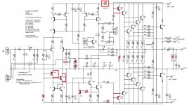
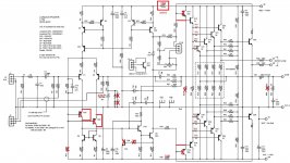
I am attaching a marked up schematic. I used 2N5551/5401 for the small ones, MJE340/350 for the VAS, MJE15034/35 for the drivers and MJL21193/94 for the outputs.
Attachments
Is c10 and r52 still in circuit?? Also noticed its current mirrow design in the long tail input stage plus cc stage at the top of input pairs.. Also look in the the vas stage a little more.. Read up on g randy slones design book he talks about such rethinking of these stages.
Regards A.
Regards A.
Would it matter if the drivers mismatched considerably? Those can.. . .MJE15034/35 for the drivers. . .
Maybe 2SC4793/2SA1837 or 2SC5171/2SA1930 could fix it?
Just a guess.
The inverse diodes do not steal current from the NFB loop.
The voltage across the NFB cap is nearly zero Vdc and nearly zero Vac.
The diodes do not pass anything more than fA.
no it does not steal current from the feedback loop,
but it steals current from the base of the pnp ltp trannie
simply because it is forward biased...
Hi AndrewT
Removing D2 and D4 greatly reduced the offset. Offset at one point was 3.5V. You questions have caused me to go back through the thread and read through all the hassle we went through trying to get this amp to work. I had hoped that the little bit of gained understanding I have acquired would help me but I see that we are really just rehashing the same territory we covered back then. I'm afraid without Struth's involvement we may never get to the bottom of what he had envisioned. PCB's are cheap to have made these days. Wasting valuable parts trying to get these working is looking a more and more like a big waste of time and effort. I agree with Jason, Kevin should have pulled the design from his website until he was able to get it working.
Ranchu said he was finally able to get a working model but was uninspired with the sound and the boards were so butchered by then that he wouldn't use them. I guess enough time had passed that I had forgotten just how hard we had tried to get this amp working. Sorry I drug all of you through it again.
Blessings, Terry
i see no need for diodes at all, i have built dozens of amp in the past and never missed those...
No, R53 is removed so they are out of circuit.Is c10 and r52 still in circuit?
Would it matter if the drivers mismatched considerably? Those can.
Maybe 2SC4793/2SA1837 or 2SC5171/2SA1930 could fix it?
Just a guess.
I don't know. I have used them in other Blameless amps without issue.
do the sums.
Imax = sqrt(P/R) = 238mAac
That is the maximum continuous base current into each output device.
Peak base current capability will be higher (*sqrt(2)) and much higher for fast transients.
Maximum output current ~ 238mAac * Number of devices * output device hFE
I'd guess for a 3pair output stage, you can easily get in excess of 30Apk to your load on long duration transients.
Probably nearer 50Apk on fast transients.
No idea what you just said. Is the correct wattage of the base stoppers hidden in there somewhere?
looking better Terry....
2.2 ohms /2 watts is fine, i have used 4.7 ohm 2w base stoppers without any problems in my amps...
No idea what you just said. Is the correct wattage of the base stoppers hidden in there somewhere?
2.2 ohms /2 watts is fine, i have used 4.7 ohm 2w base stoppers without any problems in my amps...
My Slewmaster uses 1/2 watt 4R7 base stoppers without issue. Where is the need for such large resistors in this amp? Spice shows 333uW across those 2R2 resistors.
just noticed that the Output Zobel is located after the R||L.
That means the output Zobel is physically located further away from the output stage. That increases the impedance and reduces the effectiveness of the Output Zobel.
The high frequencies that the Output Zobel is providing a load for is now 10r + 10r + 100nF, i.e. 20r+100nF
That is quite high and combined with the added inductance as above may not be stabilising the amp correctly.
ADD a second Zobel right at the output devices and connect to the nearest Power Ground connection using the shortest possible lead lengths. 5mm (1/5") max is a good guide for short, 2mm (1/12") is better.
Last edited:
as statewd earlier base stoppers can easily pass normal working currents.My Slewmaster uses 1/2 watt 4R7 base stoppers without issue. Where is the need for such large resistors in this amp? Spice shows 333uW across those 2R2 resistors.
If you were to short the output while a large signal was applied the Outputs will draw very high base currents. High dissipation base stoppers could survive this abuse.
Low dissipation base stoppers may act as fuses, maybe, but are they too slow to protect the output devices?
Q10 especially and Q8 should use very fast, low Cob devices. They are the VAS.
using
Use something like 2sc3423 or similar
using
is inappropriate, in my opinion.MJE340/350 for the VAS,
Use something like 2sc3423 or similar
Originally Posted by AndrewT View Post
The inverse diodes do not steal current from the NFB loop.
The voltage across the NFB cap is nearly zero Vdc and nearly zero Vac.
The diodes do not pass anything more than fA.
when the output is at zero volts the protection diodes are also at zero volts. They pass no current. They do not suck base current out of the -IN device. Protection diodes never see elevated voltages during any operational condition. Just like the NFB capacitor, when properly proportioned relative to the amplifier passband, never sees any significant voltage. The worst case current draw can only be in the fA range.no it does not steal current from the feedback loop,
but it steals current from the base of the pnp ltp trannie
simply because it is forward biased...
Protection diodes only pass significant current when the voltage across the NFB capacitor increases during a DC fault event. eg. the large output offset during start up.
That is a fault event that needs to be tracked down and attenuated, or even better eliminated.
Removing the protection diodes does not solve the fault event.
as statewd earlier base stoppers can easily pass normal working currents.
If you were to short the output while a large signal was applied the Outputs will draw very high base currents. High dissipation base stoppers could survive this abuse.
Low dissipation base stoppers may act as fuses, maybe, but are they too slow to protect the output devices?
I was accidentally connect amp output to ground. My amp is 150W/4Ohm and I use 5A fuse on power supply line. My base stopper resistor rating is 0.5W, the fuse burned but the amp is survive.
My Slewmaster uses 1/2 watt 4R7 base stoppers without issue. Where is the need for such large resistors in this amp? Spice shows 333uW across those 2R2 resistors.
use whatever works for you.....resistors are cheap and we are not making them by the thousands where cost is a real game changer.....
I'm just trying to learn. I'm trying to understand how to know what size is required. I didn't understand a single thing that AndrewT wrote or how to apply it to this need.
what experience you gain is the best education you can get.....
never mind if you do not understand what anyone else says,
for how sure are you that those telling you this or that
really know what they are talking about? 😀
if i were building the same amp that you are building right now,
i can tell you for sure....but for now i can only give you educated guesses
based on what i have learned from my own builds...
If you don't understand a particular sentence, or phrase, or acronym, then just ask...............I didn't understand a single thing that AndrewT wrote or how to apply it to this need.
If you really mean that you don't understand a single thing then tell me what that "single thing" is and I'll try again to explain differently.
The resistors are rated in watts. Your explanation was all about mAvac. I have no clue what you were suggesting with that.
These 1/8W resistors were simply cut in as an experiment to see if they would solve the oscillation. They were what I had on hand. They were never intended to remain nor even play music, just to try and find a way to stabilize the circuit. If they worked I would replace them with larger ones. So far, they don't seem to have had an affect.
These 1/8W resistors were simply cut in as an experiment to see if they would solve the oscillation. They were what I had on hand. They were never intended to remain nor even play music, just to try and find a way to stabilize the circuit. If they worked I would replace them with larger ones. So far, they don't seem to have had an affect.
Quote:
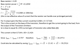
do the sums.
Imax = sqrt(P/R) = 238mAac
That is the maximum continuous base current into each output device.
Peak base current capability will be higher (*sqrt(2)) and much higher for fast transients.
Maximum output current ~ 238mAac * Number of devices * output device hFE
I'd guess for a 3pair output stage, you can easily get in excess of 30Apk to your load on long duration transients.
Probably nearer 50Apk on fast transients.
No idea what you just said. Is the correct wattage of the base stoppers hidden in there somewhere?
Attached is the longer version of Andrews calculation, maybe its easier to read this way.
Attachments
- Status
- Not open for further replies.
- Home
- Amplifiers
- Solid State
- 250w 8ohm amplifier