He signs his name at the end of each of his posts.
"Have fun, Kevin O'Connor"
If you would make a little more effort to embrace the theme of the conversation rather than nit picking it would be more helpful.
"Have fun, Kevin O'Connor"
If you would make a little more effort to embrace the theme of the conversation rather than nit picking it would be more helpful.
As I said, Struth is unique.
Kevin is not unique.
I looked back in vain and no Keven was visible, but that was to be expected since you had mentioned lack of replies.
If you had stated Struth I would not have needed to ask.
Kevin is not unique.
I looked back in vain and no Keven was visible, but that was to be expected since you had mentioned lack of replies.
If you had stated Struth I would not have needed to ask.
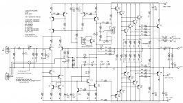
I have a question. I want to test the IPS and VAS to make sure they are working properly before I go any further. If I remove R29 and R30, short C6 and then tie the junction of R56/57 to the collector of Q7 can I power up and test the IPS/VAS? Is there anything else I will need to do?
Thanks, Terry
Thanks, Terry
Thanks Jason.
I haven't tried separating the IPS and OPS yet but I had some spare time today so I hooked up one of the boards and gave it a try. I'm testing through a variac and light bulb tester.
First thing I noticed is that it immediately starts off at about +24V offset but quickly starts dropping and passes the 0V point after about 5 seconds or so. It then gradually continues on to about -40mV which continues to rise as the amp warms up and settles at about -140mV offset. At this point I have about 19mV across a pair of the 0R33 output resistors. The is as low as I can dial it as the pot is maxed out. I checked most of the VR of most of the resistors and they are close to what I see in spice but just touching the junction of Q3B and Q5C causes the offset to jump around and the bias to double. Not sure what it going on there.
Looking closer at the schematic I see that there are two 820uf caps on the - rail and only one on the + rail. Could this explain the huge offset at turn on that gradually goes away? That would have to cause a huge turn on thump. Is there a need for both C9 and C14?
Man I wish Struth was here to answer some of this stuff.
Thanks, Terry
Last edited:
Well he did invest a bit of time creating it. 😉
The price is fair if the circuit worked. I'm really surprised about this. It seems he is a well respected author. I'm not sure why he didn't make a better effort to support this project. The fact that he still has it on his website would have me believe that he still thinks it should work.
Did you get a chance to peek at the schematic and look at the caps I asked about? I don't understand why two on one rail and only one on the other. C9, C12 & C13
those paralleled anti-phase diodes(4 off) shunting the feedback shunt cap was/is a red flag....

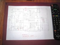
yes, i noticed that when i printed you drawing, i will post my suggested mods shortly.....
any reason why you opted for a darlington instead of a TEF?
anyway, you should remove the 470ohm resistor...
any reason why you opted for a darlington instead of a TEF?
anyway, you should remove the 470ohm resistor...
Hi Anthony,
Which 470R resistor. R1, R2?
I don't know what a darlington or TEF is so hopefully you will explain what you mean.
I just came in from doing a little more testing. I wanted to see if the offset would start so high with a load attached so I clipped a 10R-25W resistor across the output. That lowered the huge offset down to a couple volts at turn-on but the amp now surges rather than settling. My guess is if I didn't have it running through the lightbulb, I would be replacing parts right now.
I am attaching the PDF if it will help. Prints out a little clearer.
Blessings, Terry
Attachments
Too much. You changed the whole design. EF2, base stoppers, no cascodes for the LTP. Not really the direction I want to take it. My hope was to get it working as designed by finding the correct values and compensation. I don't mind pulling out the stuff that was added for dealing with theater work. Maybe I'm just barking up the wrong tree.
It's still there post 601. It was a schematic I created. I did that to one board but it required a bunch of cutting and all I had were 1/8w SMT. Probably not enough for base stoppers. It would be difficult to install through hole. I may try your suggestions on that board since I have already butchered it. I am attaching a spice file with your suggestions. I think I got them all. Runs fine in spice.
DC component:-0.0212002
Harmonic Frequency Fourier Normalized Phase Normalized
Number [Hz] Component Component [degree] Phase [deg]
1 1.000e+03 5.807e+01 1.000e+00 -0.68° 0.00°
2 2.000e+03 2.633e-04 4.535e-06 -74.30° -73.62°
3 3.000e+03 7.631e-05 1.314e-06 29.61° 30.29°
4 4.000e+03 8.786e-06 1.513e-07 152.88° 153.57°
5 5.000e+03 1.017e-05 1.751e-07 -133.16° -132.48°
6 6.000e+03 1.344e-06 2.314e-08 122.69° 123.37°
7 7.000e+03 2.528e-06 4.353e-08 68.14° 68.83°
8 8.000e+03 3.801e-07 6.546e-09 -75.37° -74.68°
9 9.000e+03 1.050e-06 1.808e-08 -132.54° -131.86°
10 1.000e+04 5.566e-07 9.585e-09 174.19° 174.87°
11 1.100e+04 3.123e-07 5.379e-09 151.83° 152.52°
12 1.200e+04 3.426e-07 5.900e-09 -178.63° -177.95°
13 1.300e+04 3.080e-07 5.305e-09 165.16° 165.84°
14 1.400e+04 1.304e-07 2.245e-09 168.53° 169.21°
15 1.500e+04 2.345e-07 4.038e-09 -149.93° -149.25°
16 1.600e+04 3.318e-07 5.714e-09 -174.13° -173.45°
17 1.700e+04 2.539e-07 4.373e-09 160.86° 161.54°
18 1.800e+04 1.396e-07 2.404e-09 170.20° 170.88°
19 1.900e+04 1.741e-07 2.998e-09 -167.98° -167.29°
Total Harmonic Distortion: 0.000473%
Attachments
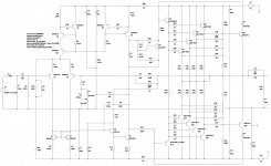
I would remove ALL the components associated with the protection, and also the output transistors leaving only one pair.
I would remove C16. Increase driver base stoppers to 150R, and output transistors bass stoppers to 4R7
I would also solder 22pF from base of Q1 to base of Q2.
I would try to simplify the circuit to just the essentials, to try to get it to work.
Then if I get it to work, add back the components removed systematically.
- Status
- Not open for further replies.
- Home
- Amplifiers
- Solid State
- 250w 8ohm amplifier