C10 & R52 create an enormous RC that may take tens of seconds to stabilise.
C10 starts off at zero volts and gradually charges to half rail voltage.
The input stage sees this changing cascode voltage during start up.
The cascode will have to rise above a threshold for the IPS to operate. That could be the time period when the offset is 24Vdc changing to 40mVdc.
C10 starts off at zero volts and gradually charges to half rail voltage.
The input stage sees this changing cascode voltage during start up.
The cascode will have to rise above a threshold for the IPS to operate. That could be the time period when the offset is 24Vdc changing to 40mVdc.
Last edited:
The inverse parallel diodes should ONLY pass current when the DC voltage across the NFB cap exceeds ~1V.Sorry, I should have mentioned that D3 and D4 have been removed. Those are an obvious mistake that we found a few pages back I will remove them for the schematic and re-post it so others don't become alarmed.
Thanks, Terry
That should never happen in a correctly operating amplifier.
Many builders and designers use these inverse parallel diodes at various location around the amplifier to limit the value of "fault voltage" and prevent further damage.
no sense using big big shunt caps in series with 1k shunt leg of the feedback network,
a 47 ufd cap in series with 1k has a corner frequency of 3.39hz, 1s this not low enough?
2 series diodes shunting the cap forms a forward path for the current on the right hand side
of the ltp pair, it steal current from the pnp base no matter small causing output offset voltage,
i believe that was the reason for its removal....i would have done that too if it were my amp.....
Add remove C10 to list.
Its resistor not active device.
Can always replace later with smaller cap,
I'm running input cascode with two resistor divider without capacitor,
Its resistor not active device.
Can always replace later with smaller cap,
I'm running input cascode with two resistor divider without capacitor,
I believe R52 and C10 were there to power the LTP cascode. Since that is removed they should probably go too.
C10 & R52 are only there to set the cascode voltage.I believe R52 and C10 were there to power the LTP cascode. Since that is removed they should probably go too.
The two 100k set the emitters to ~ half rail voltage.
The Vbe drop reduces the cascode voltage very slightly.
But the big capacitor (intended for hum & interference attenuation) slows down the cascode reaching it's operational voltage.
It would have been far better to have moved the attenuation filter (RC) to before the two 100k.
The inverse diodes do not steal current from the NFB loop..................2 series diodes shunting the cap forms a forward path for the current on the right hand side
of the ltp pair, it steal current from the pnp base no matter small causing output offset voltage,
i believe that was the reason for its removal....i would have done that too if it were my amp.....
The voltage across the NFB cap is nearly zero Vdc and nearly zero Vac.
The diodes do not pass anything more than fA.
Hi AndrewT
Removing D2 and D4 greatly reduced the offset. Offset at one point was 3.5V. You questions have caused me to go back through the thread and read through all the hassle we went through trying to get this amp to work. I had hoped that the little bit of gained understanding I have acquired would help me but I see that we are really just rehashing the same territory we covered back then. I'm afraid without Struth's involvement we may never get to the bottom of what he had envisioned. PCB's are cheap to have made these days. Wasting valuable parts trying to get these working is looking a more and more like a big waste of time and effort. I agree with Jason, Kevin should have pulled the design from his website until he was able to get it working.
Ranchu said he was finally able to get a working model but was uninspired with the sound and the boards were so butchered by then that he wouldn't use them. I guess enough time had passed that I had forgotten just how hard we had tried to get this amp working. Sorry I drug all of you through it again.
Blessings, Terry
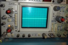
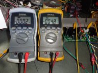
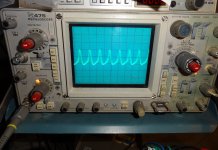
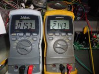
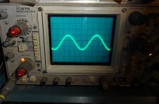
I felt like playing around with it some more to see if I could learn something. I pulled out the board that I had installed base stoppers on. I pulled the rest of the components and installed the 22R resistors in the rails so it now matches the schematic in post 659 except I also pulled R53 to disable C10 and R52. Now when I fire it up offset is very close to 0V. I have the bias turned very low during these tests. Now, as soon as I touch the DMM probe to low side of R26, the offset shoots up and so does the bias. I settles at about -200mV offset and the bias to around 12mA per device from 0mA. I see a sawtooth image on the scope. It will play a sine wave but of course it is a fuzzy one. I'm attaching some pics of the event.
Attachments
Hi Terry
I was able to cure the offset problem on my boards by lifting the diode strings (D1 - D4) from around the NFB cap (C4).
With the biasing cured, I discovered oscillation around the output stage. Cutting in base stoppers fixed that and I was able to play music. I used fairly slow output transistors (MJL21193/4) by modern standards, so I think you're dreaming if you expect to get it working without at least these stoppers - even the high power EF2 designs with parallel outputs have them.
But if you are on a mission to try and make this work without stoppers, you could try some TIP3055/TIP2955 output transistors. They are about as slow as they come (fT = 2.5MHz). But I bet it would sound pretty rubbish (but maybe it would sound great?). Alternatively try it with just a single output pair and see if that works (kinda defeats the point of the EF3 OPS).
Unfortunately I don't have my board anymore to help you with.
Hi Christian,
This board has MJL21193/4 outputs. It also has 2.2R base stoppers cut in but they are only 1/8W SMD so I doubt they will survive any music. I just used them because that's what I had on hand and wanted to see it they would stop the oscillation. As for the offset, it is very low until the oscillation or latching that is happening. Sits right at +-4mV. I removed D3 & D4 but left D1/D2 because the original Blameless has a diode there. I reduced C4 to 330u. That oscillation thing is weird. If I power up with the probe touching R26 everything is cool. I can even remove it without anything happening. As soon as I touch it again the offset shoots up as well as the bias. The same thing happens if I try to play a sine wave. It will sit at 0V offset but as soon as I add some input it jumps up. The other boards that are still EF3, do basically the same thing, but they have more offset. If I can find the culprit on this board, I may be able to fix the others.
This board has MJL21193/4 outputs. It also has 2.2R base stoppers cut in but they are only 1/8W SMD so I doubt they will survive any music. I just used them because that's what I had on hand and wanted to see it they would stop the oscillation. As for the offset, it is very low until the oscillation or latching that is happening. Sits right at +-4mV. I removed D3 & D4 but left D1/D2 because the original Blameless has a diode there. I reduced C4 to 330u. That oscillation thing is weird. If I power up with the probe touching R26 everything is cool. I can even remove it without anything happening. As soon as I touch it again the offset shoots up as well as the bias. The same thing happens if I try to play a sine wave. It will sit at 0V offset but as soon as I add some input it jumps up. The other boards that are still EF3, do basically the same thing, but they have more offset. If I can find the culprit on this board, I may be able to fix the others.
You may need to cut in driver base stoppers and/or decoupling their collectors.
Another trick is to try using slower pre drivers such as mje340/350.
Another trick is to try using slower pre drivers such as mje340/350.
Hi Christian,
The board I'm playing with right now has no pre-drivers. They have been pulled. I could install driver base stoppers where the pre-drivers were instead of the jumpers that are there now. I may try that tomorrow just for kicks. On the other boards, MJE340/350 are what are being used for the pre-drivers.
The board I'm playing with right now has no pre-drivers. They have been pulled. I could install driver base stoppers where the pre-drivers were instead of the jumpers that are there now. I may try that tomorrow just for kicks. On the other boards, MJE340/350 are what are being used for the pre-drivers.
Terry, is it possible to show on circuit diagram, the exact circuit uou have after your mods,
Maybe print out original circuit, and edit it with pen and "white-out". Then take photo of edited circuit, and repost here.
Regards
Maybe print out original circuit, and edit it with pen and "white-out". Then take photo of edited circuit, and repost here.
Regards
which output offset? The 24Vdc that lasts a few seconds or the 40mVdc that drifts a bit?................
Removing D2 and D4 greatly reduced the offset. .............
If you mean it reduces the 24Vdc offset, then yes, that is in effect a fault condition. The DC blocking capacitors will during the fault condition see a high DC voltage. The caps must be rated for the fault condition.
The inverse parallel diodes will pass current during high offsets.
Removing them will affect that.
But the diodes should NOT affect normal operation. Even D.Self uses diodes across the DC blocking cap. It allows a 10V electrolytic to be used where otherwise a 50V to 100V cap would have to be specified.
do the sums.2.2R base stoppers cut in but they are only 1/8W SMD so I doubt they will survive any music.
Imax = sqrt(P/R) = 238mAac
That is the maximum continuous base current into each output device.
Peak base current capability will be higher (*sqrt(2)) and much higher for fast transients.
Maximum output current ~ 238mAac * Number of devices * output device hFE
I'd guess for a 3pair output stage, you can easily get in excess of 30Apk to your load on long duration transients.
Probably nearer 50Apk on fast transients.
The original Blameless has D1. It is the anti-facing D3, D4 that cause the problem. Offset drops from a constant 3V to 40mV. I suppose it could just be revealing another problem but for sure, the offset drops a bunch when D3 is disconnected.which output offset? The 24Vdc that lasts a few seconds or the 40mVdc that drifts a bit?
If you mean it reduces the 24Vdc offset, then yes, that is in effect a fault condition. The DC blocking capacitors will during the fault condition see a high DC voltage. The caps must be rated for the fault condition.
The inverse parallel diodes will pass current during high offsets.
Removing them will affect that.
But the diodes should NOT affect normal operation. Even D.Self uses diodes across the DC blocking cap. It allows a 10V electrolytic to be used where otherwise a 50V to 100V cap would have to be specified.
One more thing, the board that I am toying with now that has the pre-drivers removed doesn't display that huge offset at startup. It starts at about +2V and settles at about -4mV.
Last edited:
brlmat,
What is the speaker efficiency and speaker load?
Will you be needing a 4 ohm capable amplifier that also produces significant power to 8 ohm speakers?
How many watts will a typical mains outlet withstand in your country and how many watts are consumed by your other equipment on same circuit?
The difference between a 100W amplifier and a 400W amplifier is 6db more at the speaker, which is not very impressive, so did you want watts or did you want effective louder audio, which is a somewhat different topic?
The original Blameless has D1. It is the anti-facing D3, D4 that cause the problem. Offset drops from a constant 3V to 40mV. I suppose it could just be revealing another problem but for sure, the offset drops a bunch when D3 is disconnected.
If nonstop offset:
Instead of disconnect, will it do to add another diode series?
It probably serves a useful protection and so it seems better to slack that instead of removing it entirely.
Rather than apply a quickie fixie, it may be better to fix the actual problem, which is usually at some other location.
If bursts of offset:
When there are diodes with the fb coupling cap and when there are bursts of dc offset accompanying a bass beat, that means the capacitance value is too small. Even a slightly too small cap can allow switching at the diode, causing a very tiny crispy noise from the switching, and this problem is quite easily repaired by following AndrewT's guidelines for installing the right size coupling cap (probably larger than the one you have).
Last edited:
If nonstop offset:
Instead of disconnect, will it do to add another diode series?
It probably serves a useful protection and so it seems better to slack that instead of removing it entirely.
Rather than apply a quickie fixie, it may be better to fix the actual problem, which is usually at some other location.
If bursts of offset:
When there are diodes with the fb coupling cap and when there are bursts of dc offset accompanying a bass beat, that means the capacitance value is too small. Even a slightly too small cap can allow switching at the diode, causing a very tiny crispy noise from the switching, and this problem is quite easily repaired by following AndrewT's guidelines for installing the right size coupling cap (probably larger than the one you have).
As I said above, D3, D4 may be "revealing" another problem and removing them is probably just masking it but Self didn't use them in his design and none of the other Blameless type amps I've built use them either.
This amp has not seen a music signal nor a speaker and won't until it displays that it can handle a simple sine wave without acting like it wants to blow up.
- Status
- Not open for further replies.
- Home
- Amplifiers
- Solid State
- 250w 8ohm amplifier