For testing the transient response, I use a MOSFET to switch on a power resistor acting as a load for the regulator. I have this switched load in parallel with a static load (power resistor or light bulb string depending on the amount of static load current needed). Then I watch the output voltage on an oscilloscope as the load current is stepped by turning the MOSFET on/off with a function generator. You can see the resulting oscilloscope shots in Post #1 of this thread.
~Tom
~Tom
Using a tube as the cascode device. That's a pretty interesting idea. If the tube can handle the power dissipation, you should be able to use a circuit to mine. Just increase the zener voltage on D2 such that you end up with at least 1.6 V across the regulator IC under all operating conditions (excluding the over-current condition, obviously) and you should be fine.
Test the transient response of the circuit, though. The output impedance of a tube cascode (cathode follower) is relatively high compared to that of a MOSFET follower, which may affect stability of the regulator IC.
~Tom
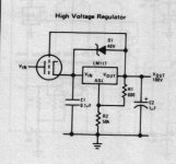
The 1970s National Data Sheet for the LM317 included a 'serving suggestion' for a HV 317 regulator with a triode to hold off some of the unregulated voltage, not unlike the "Maida".
This circuit should work well enough, provided you have some protection against static overcurrent. A suitable triode (or more Likely - a very low cost Russian power pentode or Beam Power Tube) is much better placed to cope with transient overvoltage or thermal stress events - that might blow a FET to short.
Check out the ebay prices and the performance of the 6П36C (6P36S), for example.
Attachments
For testing the transient response, I use a MOSFET to switch on a power resistor acting as a load for the regulator.
~Tom
I have 2 of the regulators assembled, but not yet tested. I was thinking of biasing the MOSFET into conduction for a 25mA load and sweeping from 1kHz to 2MHz. This will give you a pretty good idea of the impedance and phase angle from which you can determine whether the control loop is over- or under-damped.
I have the kit to do it for low voltage devices, high voltage is a different kettle of fish. Don't want to have to repair the front end of my spectrum analyzer!
The 1970s National Data Sheet for the LM317 included a 'serving suggestion' for a HV 317 regulator with a triode to hold off some of the unregulated voltage, not unlike the "Maida".
Very cool. Yeah, that'll work. It'll suffer the same disadvantages as the regular Maida circuit - 10 mA needed through the LM317 - but it is handy to be able to dissipate the majority of the power in the tube.
That circuit should work just fine with the LT3080 and my 21st Century Maida Regulator. Just increase the breakdown voltage on the Tranzorb (D3) to 30 V or so. The regulator IC can handle up to 36 V (40 V ABS MAX).
On the topic of MOSFET ruggedness: A lot of my development effort actually went into ruggedizing the 21st Century Maida Regulator to ensure that it can handle the various overstresses found in tube amplifiers. The nasty high di/dt spikes caused by loose tube sockets are common killers of semiconductors. I managed to get my 21st Century Maida to handle those. But, of course, extreme over-voltages or over-current conditions (short circuits) will cause fireworks and dead silicon in a hurry. Tubes are a bit more forgiving of this.
I have the kit to do it for low voltage devices, high voltage is a different kettle of fish. Don't want to have to repair the front end of my spectrum analyzer!
Been there, done that. I have a rig for testing my Universal Filament Regulators - low voltage circuits. That's pretty trivial. However, I tried using the same rig for testing the Maida Regulator which prompted some serious fireworks in my testing rig. I find the load transient test you describe to be the best solution for high-voltage circuits. You can also use a single-ended class A tube amplifier as a load. Sweep the input frequency to the amp and measure the resulting B+ current draw and voltage droop vs frequency. That's how I ended up measuring the output impedance of the 21st Century Maida Regulator. As long as any peaks in the output impedance have reasonably low Q (<1), the circuit is stable with a reasonable phase margin. I generally aim for Q = 0.7.
~Tom
Last edited:
Regarding the zener, it will limit the Vg of the cascode tube to 30-ish V, right? Then looks like in some cases where high Vin-Vout and low loading current present, tubes like 6С19П might not work?
Duong,
Duong,
Last edited:
I got curious and looked at triode strapped 6L6GC and KT88 just as examples. Even at moderate currents (200 mA), the voltage across the tube is well over 100 V for values of Vgk that would allow the LT3080 to regulate. This severely limits the amount of current the regulator will be able to supply. So if you don't need that much supply current, the tube cascode may work well. But then so with a MOSFET with a small heat sink.
Interesting thought though.
~Tom
Interesting thought though.
~Tom
Regarding the zener, it will limit the Vg of the cascode tube to 30-ish V, right? Then looks like in some cases where high Vin-Vout and low loading current present, tubes like 6С19П might not work?
Duong,
If you need more grid bias voltage, for low current, you can always add a Vbe-multiplier (in the cathode wire) to add any voltage you like.
A Zener can do the same thing, but adds unpredictable amounts of noise.
Endstage Beam Power Tubes like 6L6, KT88 etc are designed for high voltage operation, and won't serve for high current.
The story is very different for purpose-designed series pass triodes:
6AS7 or 6080 can do 300mA for about 70V headroom and 10V-20V bias;
And if we are trying to feed some steaming beast, call out for the Ulyanov 6C33C (6S33S), who will answer with 600mA at 60-80V headroom.
If that's not enough, Parallel more bottles, get any unreasonable amount of current!
The other nice thing about pass-triode regulators: you can rectify the raw dc with SiC rectifiers, and still get the slow rise supply voltage that vacuum rectifiers give.
Last edited:
The story is very different for purpose-designed series pass triodes:
6AS& or 6080 can do 300mA for about 70V headroom and 10V-20V bias;
The other nice thing about pass-triode regulators: you can rectify the raw dc with SiC rectifiers, and still get the slow rise supply voltage that vacuum rectifiers give.
I like those aspects as well. Looking at the data sheet for the 6080, it appears it can only handle 125 mA per section, though. So to get to 300 mA, you'll need at least three sections (two tubes) in parallel). But point well taken. It's always better when you use a tube designed for the purpose.
~Tom
For the plain vanilla Philips 6080, I link to above, the ABS MAX is 125 mA per cathode (page 2 of the data sheet). The Raytheon 6080WA can handle 150 mA and the 6080WB 200 mA per cathode.
There's probably some wiggle room there, but in a pass triode, I don't think I'd recommend exceeding ABS MAX.
~Tom
There's probably some wiggle room there, but in a pass triode, I don't think I'd recommend exceeding ABS MAX.
~Tom
Yes, the ratings are all different! Just pick the version to suit the maximum demand for a given design.
If our load demand can be satisfied with the weedier 125mA version, we can also reduce the min. voltage overhead a little, to 60V.
I agree, there's no need to breach the maximum ratings in that position. For any load continuously drawing 250mA or more, the 6C33C would be a better bet anyway - the derating will give us long & reliable lifetime.
Hi Tom, and Happy New Year!
Still looking at your regulator. Have you verified a need for the 1N4007 diode, anode to ground and cathode to regulator output? Or are you just being cautious? Nothing wrong with that if so - it's small and cheap. But I'm trying to identify a circumstance where the regulator output could go negative.
Just curious.
Have you verified a need for the 1N4007 diode, anode to ground and cathode to regulator output? Or are you just being cautious?
The diode on the output (D5) is to protect the regulator IC in the event that something drives the regulator output negative. It's an inexpensive cover-your-a** feature. It may also provide some protection against spikes caused by loose connections in tube sockets and such.
I originally designed the 21st Century Maida Regulator to supply my 300B amp. In one of the prototypes for one of my 300B amps, the negative bias supply would drive the B+ supply negative if the B+ went away before the bias supply. As these were two completely separate supplies (the bias supply being an HP lab supply), this was a real possibility. Even through the drive impedance of the bias supply was rather high, I wasn't quite comfortable allowing the regulator output to be driven to -225 V, hence, I chose to implement the reverse bias protection diode in the 21st Century Maida Regulator. I figured the added cost of the diode was well worth it in terms of peace of mind. I left it in the final circuit for the same reasons.
You often see the reverse voltage protection diodes in low voltage supplies as well.
~Tom
Last edited:
Thanks for your reply, Tom. The diode sounds like a reasonable precaution considering the negative bias supply.
The protection diodes I'm familar with in low voltage supplies such as the LM317 go from the output to the adjust pin, though, not ground. Can you point me to a low voltage design that employs one between the output and ground?
The protection diodes I'm familar with in low voltage supplies such as the LM317 go from the output to the adjust pin, though, not ground. Can you point me to a low voltage design that employs one between the output and ground?
The various LM317 data sheets do indeed show the diode from OUT to IN on the IC to protect in the situation where the output voltage is higher than the input voltage (happens during power-down). I also seem to recall some of the application schematics - typically those of lab supplies - including the reverse biased diode on the output.
If I don't have it from a 3-terminal voltage regulator data sheet, I'm sure I've seen it in the service manuals for my HP power supplies. The HP6237B has protection diodes, for example.
In cases where the load may behave rather differently than a resistor, the reverse biased diode is cheap insurance. Especially in high energy circuits like those my Maida Regulator are supposed to supply.... 🙂
~Tom
I also seem to recall some of the application schematics - typically those of lab supplies - including the reverse biased diode on the output.
Yes, and with reason...
1. Take two lab supplies, preferably different types (and different max amperages)
2. Put them in series so you have more voltage to play with.
3. Now short-circuit the supplies.
Poof! the smallest supply dies... unless it has this diode 🙂
Gents, my question related to the diode between the output and ground, not the output and input.
- Home
- Vendor's Bazaar
- 21st Century Maida Regulator