Forgot to mention that the vbe.is a.little closer 2sc3503e to the.ksa1381estu than the ksc3503dstu.. The slewmaster spooky liked 2sc3503e at 5.5ma. Waiting for your recommendation.
I am not sure what producer is for 2SC3503 or 2SA1381 from reichelt as the photo says nothing and the data says nothing and I don't think it's Sanyo.
If you can get KSA1381D version with lower hfe it's better.
I happen to have a few 1381d , hfe 97 at 5,00ma with atlas peak dca75pro,
thanks dadod
BR.Toni
thanks dadod
BR.Toni
Correct me if I'm wrong, but I would like to highlight what seems to me as a biasing error on input transistors Q11 - Q12.
In order to obtain minimum THD for a silicon Bjt transistor, a Vce voltage of at least 1V ("knee voltage") is needed.
If Vce < 1V the collector-base junction is not properly reverse biased.
|Vce| on Q11 is equal at |Vbe| on Q3 (voltage drop on R45 and R46 is negligible) .
Similarly |Vce| on Q12 = |Vbe| on Q4.
So |Vce| on Q11 - Q12 is about 0.6V that is less than 1V.
I know that THD is very low in LTspice and amplifiers built according with this schematic work fine, but there might be room for further improvements.
What do you think?
Are Q11 - Q12 biased on saturation zone?
Thanks!
Correct me if I'm wrong, but I would like to highlight what seems to me as a biasing error on input transistors Q11 - Q12.
In order to obtain minimum THD for a silicon Bjt transistor, a Vce voltage of at least 1V ("knee voltage") is needed.
If Vce < 1V the collector-base junction is not properly reverse biased.
|Vce| on Q11 is equal at |Vbe| on Q3 (voltage drop on R45 and R46 is negligible) .
Similarly |Vce| on Q12 = |Vbe| on Q4.
So |Vce| on Q11 - Q12 is about 0.6V that is less than 1V.
I know that THD is very low in LTspice and amplifiers built according with this schematic work fine, but there might be room for further improvements.
What do you think?
Are Q11 - Q12 biased on saturation zone?
Thanks!
Q11 with Q3 and Q12 with Q4 are so called supper pairs. This is not only simulated amp but built and measured with very low distortion. Try to read more, there in this thread are some measured result for 200 W version.
Q11 with Q3 and Q12 with Q4 are so called supper pairs. This is not only simulated amp but built and measured with very low distortion. Try to read more, there in this thread are some measured result for 200 W version.
I've already specified in my previous post that I know that there are real amps built with your schematic and not only simulations on LTSpice.
I've also seen THD measurements on two assembled amps.
If I correctly remember the same super pairs configuration has been used in another schematic posted by a diyaudio's member (Manso?), but I never seen this particular configuration in other schematics.
I've seen instead many cfa amps with input transistors in a diamond configuration with collectors connected to rails power.
Sorry, but I didn't know anything about super pairs configuration.
I'll try to find some info on the net.
Many thanks!
... on input transistors Q11 - Q12.
In order to obtain minimum THD for a silicon Bjt transistor...
What circuit do you refer to?
There is >1000 posts and various schematics with transistors differently numbered.
Best wishes
David
Ok, just wanted to confirm.
Last edited:
What circuit do you refer to?
There is >1000 posts and various schematics with transistors differently numbered.
Best wishes
David
This one:
http://www.diyaudio.com/forums/solid-state/243481-200w-mosfet-cfa-amp-78.html#post4309544
Q11 with Q3 and Q12 with Q4 are so called super pairs...
Hi Damir
I am interested too because this use of a super pair is new to me.
Usually the front transistors just act as level shifters, diode connected - or sometimes actual diodes are used.
I haven't simulated this yet but I expect you will have, does the super pair connection actually make much difference?
If it helps then I would expect the IC people would have some examples, is it used in any other amps?
Or is there any reference for it?
Best wishes
David
Hi David,
There was some discussion about super pair on some of the thread, I don't remember were. It is called Baxandall super pair or Boxon, but Walter Jung documented that even before there was explained by someone else, don't remember. As you said there so many post not easy to find something specific.
I prefer super pair over diamond
 . There is no big difference in THD, just in simulation I've got a bit lower with the supper pair and for me it looks nicer 😀. A diamond could be bootstraped or simple.
I use supper pair in my GainWire mk2 and mk3 and I like the sound.
Best wishes, Damir
Your link took me to post1041. There is no sch.
Really? The link in #1047 took me to #775 and this schematic: http://www.diyaudio.com/forums/atta...7278-200w-mosfet-cfa-amp-200w-cfa-vmosfet.zipYour link took me to post1041. There is no sch.
There was some discussion about super pair on some of the thread, I don't remember w[h]ere...
Yes, I have seen the super pair (or Baxandall pair) before, just not used as the input to a CFA.
It looks to me that the front transistors would basically function only as level shifter in a CFA, but that's without any analysis - just first impression.
One more simulation to do😉
Best wishes
David
Really? two. I ended up at #1001 where there really is a schematic that fits the description.
Last edited:
Very strange.. For me it's ok.Your link took me to post1041. There is no sch.
Anyway the schematic is at page 78 post 775, the same that is linked on the first page of this thread.
In the meantime I've found this thread about Baxandall Super Pair:
http://www.diyaudio.com/forums/solid-state/166306-origins-baxandall-super-pair.html
Your link takes me to the top of pg 22, i.e. the last page of this thread, because I have set my profile to 50 posts per page. You have to link to the specific post and remove the page reference.
Your link took me to post1041. There is no sch.
Really? The link in #1047 took me to #775 and this schematic: http://www.diyaudio.com/forums/atta...7278-200w-mosfet-cfa-amp-200w-cfa-vmosfet.zip
Yes, I have seen the super pair (or Baxandall pair) before, just not used as the input to a CFA.
It looks to me that the front transistors would basically function only as level shifter in a CFA, but that's without any analysis - just first impression.
One more simulation to do😉
Best wishes
David
Really? two. I ended up at #1001 where there really is a schematic that fits the description.
Very strange.. For me it's ok.
Anyway the schematic is at page 78 post 775, the same that is linked on the first page of this thread.
In the meantime I've found this thread about Baxandall Super Pair:
http://www.diyaudio.com/forums/solid-state/166306-origins-baxandall-super-pair.html
The bad link takes Members to the wrong Thread unless they have exactly the same set up as the original poster.Your link takes me to the top of pg 22, i.e. the last page of this thread, because I have set my profile to 50 posts per page. You have to link to the specific post and remove the page reference.
Instead for a good link:
Right Click on the post number and "Save target as..." (in IE), or "Save Link As..." (in Firefox). The other Browsers probably have a different name for the save as.
Then paste that address into your post.
Last edited:
The bad link takes Members to the wrong Thread unless they have exactly the same set up as the original poster.
Instead for a good link:
Right Click on the post number and "Save target as..." (in IE), or "Save Link As..." (in Firefox). The other Browsers probably have a different name for the save as.
Then paste that address into your post.
Andrew, we had here that discussion about links, pleas stop with this, this thread is about amp.
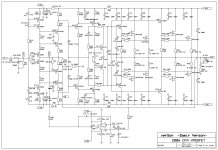
I would like to offer 200W CFA version to interested ones.
This is actual version Richard March measured some time ago with some overload protection and layout improvements.
I made layout with possibility to have three configuration.
1. pure CFA with two way how to connect the feedback resistors, parallel or series. As this quite powerful amp some power dissipates on the feedback resistor, that's why parallel or series combination. The serial combination overcome resistor voltage distortion but have longer feedback path.
2. By adding a buffer to the - input this amp is transform in to VFA.
3. Adding one more buffer it can accept balanced input.
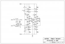
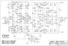
Here are the schematics. First one is of the main amp board and second one is the piggy board used instead the feedback resistors boards.
This is actual version Richard March measured some time ago with some overload protection and layout improvements.
I made layout with possibility to have three configuration.
1. pure CFA with two way how to connect the feedback resistors, parallel or series. As this quite powerful amp some power dissipates on the feedback resistor, that's why parallel or series combination. The serial combination overcome resistor voltage distortion but have longer feedback path.
2. By adding a buffer to the - input this amp is transform in to VFA.
3. Adding one more buffer it can accept balanced input.
Here are the schematics. First one is of the main amp board and second one is the piggy board used instead the feedback resistors boards.
Attachments
Last edited:
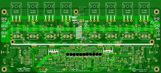
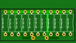
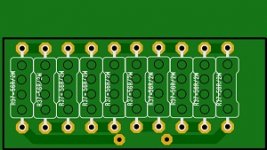
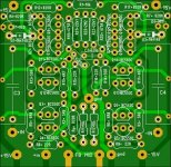
Here is the layouts of the main amp board, two piggy feedback boards and VFA and balanced input board.
Attachments
No, I won't stop this. There was a bad link. Five Members found different destinations. I explained how to not arrive at posting a bad link. On topic !Andrew, we had here that discussion about links, pleas stop with this, this thread is about amp.
If you don't like it that Five members need to post their results of that bad link, then you could report the offending bad link post and ask for it to be removed. You could then post the correct link.
Last edited:
- Home
- Amplifiers
- Solid State
- 200W MOSFET CFA amp