For what it's worth, the ljm board seems much easier to modify, or repair because of the through hole components. He's also here for support if needed.
Last edited:
I don't know about L15D international agency price.
They are about 210 RMB. ABOUT 33USD FOR 2 PCS Stereo.
I cannot find them cheaper than here:
L15D 300W+300W Class D power amplifier kit IRS2092 IRFI4019H by LJM-in Amplifier from Consumer Electronics on Aliexpress.com | Alibaba Group
I'm not a EE type of user like most in this thread are. Does this kit include good enough parts without changing them out? I see he offers to sell built kits for 15.00 more, which is probably what I would do
If you are not experienced, a built kit is probably best.
yes, but how about the quality of the parts he uses?
When you consider that LJM is on here and is happy to defend and explain his designs, then it is likely that the parts are OK.
Zoe Tsang, the vendor of the kits was one of LJM's preferred sellers so I am sure the pre built and tested boards will be OK.
Zoe Tsang, the vendor of the kits was one of LJM's preferred sellers so I am sure the pre built and tested boards will be OK.
When you consider that LJM is on here and is happy to defend and explain his designs, then it is likely that the parts are OK.
Zoe Tsang, the vendor of the kits was one of LJM's preferred sellers so I am sure the pre built and tested boards will be OK.
I did not know that. thanks.
I bought IRS2092 module but for some reason I like hifimediy amp on TA2050 much better. It just gives this highly detailed yet smooth sound, like a good tube amp. The only problem with this hifimediy amp (T3S) is that after changing coils it doesn't want to start the relays when I use the power switch connected to the amp's board (after SMPS). The relays only kick in when I use the main switch before SMPS. Has anyone seen similar behaviour before?
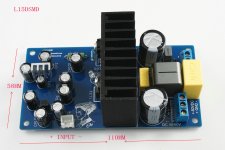
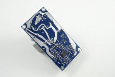
SMD L15DSMD Version, about $10, 65 RMB.
😀
😀
Attachments
Last edited:
SMD L15DSMD Version, about $10, 65 RMB.
😀
Looks good ! any measurements ?
Cheers ,
Rens
Looks good ! any measurements ?
Cheers ,
Rens
Have measured. Actually a few years ago had a similar design.
Just, I contrast, L15D DIP. I prefer L15D.
Maybe someone like SMD, of course.
At least 50 + - v digital power amplifier is not much heat.
If L25D L20D L30D, circuit board has a high temperature. I will still use the metal resistance capacitance.
😀 And I want to say, I like the British power amplifier,
MF QUAD NAIM.
The Englishman's design is really good. Is probably the best in the world.
Last edited:
In case you missed it, these need a small load on secondary outputs to be stable. Put 150ohm 5w resistor on secondary low voltage outs.
Ok, I am finally at the point where I can try this out..
Looking at the earlier diagram I didn't see the secondary outputs..
http://www.diyaudio.com/forums/class-d/275915-200w-irs2092-amp-20-a-9.html#post4365096
Did you have those marked on another drawing?
I appreciate the help.
Thanks again,
Troy
=================
EDIT:
Never mind, I found the data sheet on Parts-Express..
Thanks though!
EDIT2:
Where is the best place to order the connectors and pins for the power supply AND the amplifier? Or is it better to remove the pins and install cinch terminals?
=================
Last edited:
They are 0.156in pitch header connectors according to spec sheet. There are 6 pin headers for input and output and a 4 pin output for secondary voltage, and 2 pin for remote shutoff. Probably Mouser or Digikey. Look for Molex brand rectangular female header plugs.
Where is the best place to order the connectors and pins for the power supply
You want these:
6-PIN CONNECTOR W/HEADER, 0.156" | All Electronics Corp.
Fits right on the PS pins. They also sell similar with other number of pins. Just look around the web site.
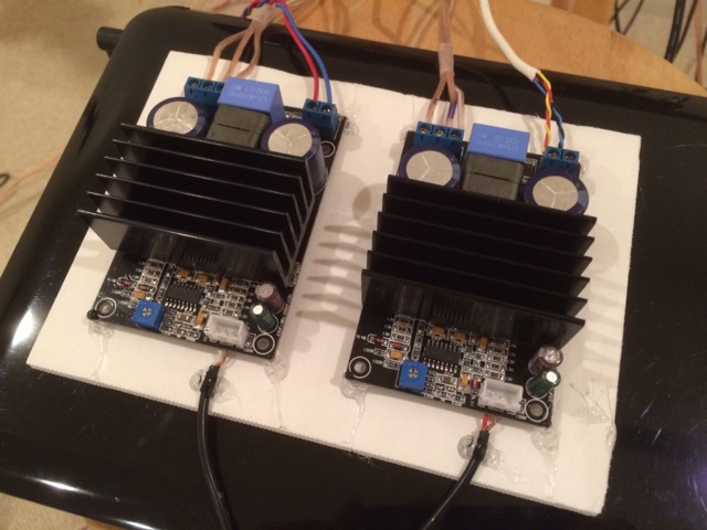
I see in the picture that you used the left pin for audio + on both modules. Does it matter which input you use? Left or right? Does the module sum the channels or is only the left side connected?
Side question, what is the cable on the top of the SMPS that is tied down and terminated with the red connector? Is that an on / off type circuit? Maybe LED status lead?
Thanks again.. I have limited space for construction so I have to have all the research and prep done before I arrange the use of space.
Troy
I think I looked at the traces and determined that the left ch input is the functional one. I forget how, but probably see that right is either grounded or n/c.
I don't know what you are referring to? SMPS? Red?Side question, what is the cable on the top of the SMPS that is tied down and terminated with the red connector? Is that an on / off type circuit? Maybe LED status lead?
Yes on the tops of the abletec smps there is a pair of wires in a black insulator tube that leave the middle of the smps go towards the ac input section, are tied down to the top of an inductor then turns back up towards the DC output section. It stops about half way and is terminated with a red plastic connector.
To me it looks like it would have been something like a LED supply for status / fault or maybe an on / off trigger.
To me it looks like it would have been something like a LED supply for status / fault or maybe an on / off trigger.
Is is time for a separate thread on the Abletec supply? Each time I get an update from this thread it is about the Abletec SMPS.
Is is time for a separate thread on the Abletec supply? Each time I get an update from this thread it is about the Abletec SMPS.
I have 2 of the 53V units in dual mode and would like to compare notes; affordable dual mode supplies at this voltage are few and far between. Don't want to say much more, since this is officially wrong thread (yet related since the voltage matches the amp on topic).
- Home
- Amplifiers
- Class D
- 200W IRS2092 Amp for $20