I'm glad you like him.
I think a reliable amplifier, it takes a long time.
In a few years time, I tried many times post L15D to smd slice of a smaller size.
The result is that their output signal distortion is very high,
That is why I have been using single circuit board, into the cause of the dip resistance.
In the absence of the input signal, measure output OUT GND. 400-500 k can understand digital power amplifier distortion of PWM graphics.
May be unable to distinguish between the ears.
The following several products are failure.
They can also have music.
In spare time, I would to buy a comparison test of the first page of the amplifier, if someone is interested in seeing?
I'm a bit lost in your translation , but L15D's are still my favorite amps !
running at least 6 hours a day , never had any problem , power supply is Connex SMPS2000RxE at +/- 55 Volts for 5 channel AV Amp with Emotiva UMC-1 as processor and Tannoy 15" DC's as speakers.
Very nice and dynamic sounding combination !
Cheers ,
Rens
I prefer the traditional way. Such as transformer + large capacitance.(Their lifespan may be same length as the tortoise)
I don't like slice resistance capacitance. I think they are cheap, but the reliability, life and accuracy. Resistance than metal
😀
For example, DSI 225.
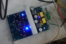
Although I don't like the circle inductance, they have too much EMI harm to human body.
Attachments
Last edited:
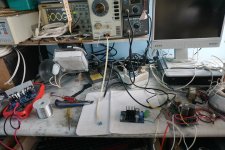
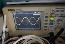
A little busy. Simple test for a moment, and I think the same.
Set as high frequency, measuring OUT GND graphics.USE DC+ -50V
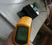
Could not be locked frequency, place 10 minutes after the measured temperature, the radiator about 60 degrees Celsius.
The indoor temperature of 29 degrees Celsius
PWM estimates that about 700-800 k set.
Graphics is a mess, I also can't see clearly.
Set as high frequency, measuring OUT GND graphics.USE DC+ -50V
Could not be locked frequency, place 10 minutes after the measured temperature, the radiator about 60 degrees Celsius.
The indoor temperature of 29 degrees Celsius
PWM estimates that about 700-800 k set.
Graphics is a mess, I also can't see clearly.
Attachments
Last edited:
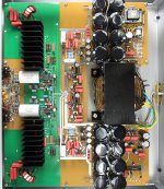
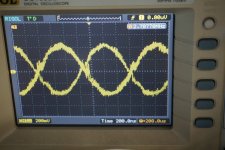
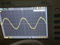
Comparing measurement is L15D
The same power supply, DC + - 50 v
The same test environment.
The indoor temperature of 29 degrees Celsius
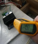
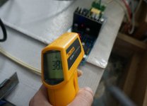
Probe placed OUT GND position, can very clearly see the 490 k frequency PWM signal,
I like this kind of image it with IRAUDAMP7D basically the same, there is no obvious difference.
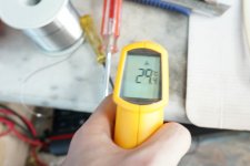
It has been run. For a long time, I hand touched, almost no obvious temperature.
Test the temperature of about 38 degrees Celsius.
It is very beautiful. This is a simple, anyone can do the test.
It can be tested repeatedly,
The same power supply, DC + - 50 v
The same test environment.
The indoor temperature of 29 degrees Celsius
Probe placed OUT GND position, can very clearly see the 490 k frequency PWM signal,
I like this kind of image it with IRAUDAMP7D basically the same, there is no obvious difference.
It has been run. For a long time, I hand touched, almost no obvious temperature.
Test the temperature of about 38 degrees Celsius.
It is very beautiful. This is a simple, anyone can do the test.
It can be tested repeatedly,
Attachments


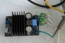
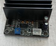
I don't have the black amplifier to test THD's interest,
Because it and I used to post film version of the same design, very ugly.
In order to reduce waste, I pulled down its chips and MOSFET, and lc.
These parts are still valuable.
The new circuit board will allow them to play a better level

Because it and I used to post film version of the same design, very ugly.
In order to reduce waste, I pulled down its chips and MOSFET, and lc.
These parts are still valuable.
The new circuit board will allow them to play a better level
A little busy. Simple test for a moment, and I think the same.
Set as high frequency, measuring OUT GND graphics.USE DC+ -50V
Could not be locked frequency, place 10 minutes after the measured temperature, the radiator about 60 degrees Celsius.
The indoor temperature of 29 degrees Celsius
PWM estimates that about 700-800 k set.
Graphics is a mess, I also can't see clearly.
Thanks for testing this amp. Are you saying it is no good because it can't lock on a frequency? What are you using for the load? A 200w 8R resistor?
What is max power you are able to get out of this amp?
I may have to get your amp - looks really nice with cooler temps.
Small pot near input is for adjustment of switching frequency isn't it? Can't the 700-800khz be lowered to 400khz?
Thanks for testing this amp. Are you saying it is no good because it can't lock on a frequency? What are you using for the load? A 200w 8R resistor?
What is max power you are able to get out of this amp?
I may have to get your amp - looks really nice with cooler temps.
I didn't say it is not good.
The test and no signal input, no audio signal output. No music, no load.
I designed a lot of class D amplifier, but 90% is I threw away. They all have a similar phenomenon.
The PWM frequency processing. As far as I know, DIY digital amplifier by more than 95% this kind of phenomenon.
This a black board is not the worst, it should have a voice.
This is a simple, anyone can test test.
PWM amplifier graphics can illustrate the design is good.
If you are interested, I can take some IR test of the original design of figure, IRAUDAMP7S give it to you.
PWM graphics oscillation is serious, can cause MOSFET temperature increases, the signal distortion increase.
Last edited:
Small pot near input is for adjustment of switching frequency isn't it? Can't the 700-800khz be lowered to 400khz?
After I received a parcel didn't change anything.
700-800 k is my guess, in fact, I don't know how much is the working frequency, because of its graph is a mess.
In addition, this is not the problems caused by frequency, L15D can also work in higher frequency.
Pay attention to look at the picture, the waveform of coarse and fine. Coarse graphical representation, it has a high high frequency interference.
I can do a L15D higher frequency test, maybe you can more easily.
Let's have a look at the IR engineering model test, as a comparison.
The original IRAUDAMP7S - 150.
It is basically the same as the L15D
Pay attention to the rough graph line, and fine. More thick graphics is more high frequency interference
Attachments
Higher switching frequency like you mentioned 700-800khz would cause higher temperature. On both your L15 and IRAUDAMP7S it looks like frequency is fixed,set by resistor not pot. I believe ~400khz is adviced both in china advertisement for these ampboards and by IR, maybe frequency is more obvious on inductor, befor filtering.
If people buy the ampboards with pots and cannot measure frequency they probably need to look at IRAUDAMP's and set pot at resistance advised there in datasheet or replace pot for that fixed resistor value? Anyway that was advise given for Liteamp, there optimum switching frequency for mainly through hole ampboard was a little below 400khz.
If people buy the ampboards with pots and cannot measure frequency they probably need to look at IRAUDAMP's and set pot at resistance advised there in datasheet or replace pot for that fixed resistor value? Anyway that was advise given for Liteamp, there optimum switching frequency for mainly through hole ampboard was a little below 400khz.
So are we saying that If the pot is adjusted. We can get the PWM oscillator down to 400kHz approx and these boards will run cool? Or are we saying that the first thing to do is adjust the pot for 400kHz then look for the other problems?
I can understand why LJM-LJM is investigating and why the L series are a better bet for most but this thread is about the cheapies, even if the final consensus is that it is badly designed/laid out and should be avoided at all costs.
I can understand why LJM-LJM is investigating and why the L series are a better bet for most but this thread is about the cheapies, even if the final consensus is that it is badly designed/laid out and should be avoided at all costs.
If I select higher switchingfrequency with other classD ampboards the temperature goes up significantly, which makes sense.
Iraudamp7S has adjustment pot, Iraudamp7D has fixed resistor. Instructions for connection for both, mention checking switching/self oscillating frequency and make certain it is 400khz +/- 25khz. The ampboard you bought is sort of clone/copy and I think I remember reading setup advise in aliexpress ad too, LJM checked and the producer/seller doesn't check frequency themselves so it seems. IR writes (several DMM have frequency function too and might be good enough?):
Switching Frequency Test:
11. With an oscilloscope, monitor switching waveform at test points VS1 & VS2 Adjust P1A &
P1B to change self oscillating frequency to 400kHz ± 25kHz.
Note: To change self-oscillating switching frequency, Adjust the potentiometer
resistances of P11A and P11B for CH1 and CH2 respectively.
Self-Oscillating Frequency
Self-oscillating frequency is determined by the total delay time along the control loop of the
system; the propagation delay of the IRS2092, the MOSFETs switching speed, the time-constant
of front-end integrator (P1, R7, R11 R8, C4, C6, C7). Variations in +B and –B supply voltages
also affect the self-oscillating frequency.
The self-oscillating frequency changes with the duty ratio. The frequency is highest at idling. It
drops as duty cycle varies away from 50%.
Adjustments of Self-Oscillating Frequency
Use P1 & R11 to set different self-oscillating frequencies. The PWM switching frequency in this
type of self-oscillating switching scheme greatly impacts the audio performance, both in absolute
frequency and frequency relative to the other channels. In the absolute terms, at higher
frequencies distortion due to switching-time becomes significant, while at lower frequencies, the
bandwidth of the amplifier suffers. In relative terms, interference between channels is most
significant if the relative frequency difference is within the audible range.
Normally, when adjusting the self-oscillating frequency of the different channels, it is suggested to
either match the frequencies accurately, or have them separated by at least 25kHz. Under the
normal operating condition with no audio input signal, the switching-frequency is set around
400kHz in the IRAUDAMP7S.
If I select higher switchingfrequency with other classD ampboards the temperature goes up significantly, which makes sense.
Iraudamp7S has adjustment pot, Iraudamp7D has fixed resistor. Instructions for connection for both, mention checking switching/self oscillating frequency and make certain it is 400khz +/- 25khz. The ampboard you bought is sort of clone/copy and I think I remember reading setup advise in aliexpress ad too, LJM checked and the producer/seller doesn't check frequency themselves so it seems. IR writes (several DMM have frequency function too and might be good enough?):
Switching Frequency Test:
11. With an oscilloscope, monitor switching waveform at test points VS1 & VS2 Adjust P1A &
P1B to change self oscillating frequency to 400kHz ± 25kHz.
Note: To change self-oscillating switching frequency, Adjust the potentiometer
resistances of P11A and P11B for CH1 and CH2 respectively.
Self-Oscillating Frequency
Self-oscillating frequency is determined by the total delay time along the control loop of the
system; the propagation delay of the IRS2092, the MOSFETs switching speed, the time-constant
of front-end integrator (P1, R7, R11 R8, C4, C6, C7). Variations in +B and –B supply voltages
also affect the self-oscillating frequency.
The self-oscillating frequency changes with the duty ratio. The frequency is highest at idling. It
drops as duty cycle varies away from 50%.
Adjustments of Self-Oscillating Frequency
Use P1 & R11 to set different self-oscillating frequencies. The PWM switching frequency in this
type of self-oscillating switching scheme greatly impacts the audio performance, both in absolute
frequency and frequency relative to the other channels. In the absolute terms, at higher
frequencies distortion due to switching-time becomes significant, while at lower frequencies, the
bandwidth of the amplifier suffers. In relative terms, interference between channels is most
significant if the relative frequency difference is within the audible range.
Normally, when adjusting the self-oscillating frequency of the different channels, it is suggested to
either match the frequencies accurately, or have them separated by at least 25kHz. Under the
normal operating condition with no audio input signal, the switching-frequency is set around
400kHz in the IRAUDAMP7S.
I use a fixed resistance. Frequency of about 450 k.
I don't know about other designers. I am not adjust or change it.
I bought a couple of these Yuan Jing IRS2092 boards (each is basically 1/2 if an IRAUD7). I paid all of $14 each, shipped, earlier this year. As mentioned above, the oscillation frequency trimmers hadn't been adjusted at all, both were in the middle of their ranges and both boards oscillated at about 780kHz. In fact, one of the trimmers was even the wrong value - one was the correct 2k ohm part specified by IR, the other was a not-even-close 50k trimmer! Not a lot of careful checking done when these were made, I guess.
Surprisingly, they didn't get even warm at idle, even when clocked at nearly double their suggested frequency! I was even powering them from +/-53VDC, using the surplus Abletec power supplies from Parts Express. (BTW, don't believe the nonsense about these Abletec supplies being "cheap" designs, they are extremely well built and work really well, provided they are run with the needed minimum loads on their lower voltage supplies).
I adjusted the oscillation frequencies using an oscilloscope. Just look at the ripple waveform at the speaker output, and adjust so that the period (the time between two peaks) is about 2.5usec (I set one for 2.4usec, the other for 2.6usec to avoid any possible audio beat tones). I replaced the incorrect 50k trimmer with a 10turn 10k trimmer (the closest I had in the junk drawer) to get there.
Bwaslo,
Thanks for the feedback - so once pots are adjusted for correct frequency do they sound good? Do they run cooler? I'm glad that Abletec business is all straightened out. I just got my 150ohm power resistor for the low voltage load.
Thanks for the feedback - so once pots are adjusted for correct frequency do they sound good? Do they run cooler? I'm glad that Abletec business is all straightened out. I just got my 150ohm power resistor for the low voltage load.
They sound pretty good to me. I'm making a "Travesty" amp with them (putting a tube front end on it, which I'm sure some tube or anti-tube enthusiasts will consider to be a travesty!).
Btw, you don't really need a power resistor. A 1/2 watt part will do for the 7.5V supply, 1/4w is enough for the 5.6V supply (both 150 ohm parts). It's just V×V/R.
Btw, you don't really need a power resistor. A 1/2 watt part will do for the 7.5V supply, 1/4w is enough for the 5.6V supply (both 150 ohm parts). It's just V×V/R.
I have a couple of these little amp boards that I someday plan to check out and put to use. Thanks bwaslo for posting about the timing to look for in the output ripple. Great tip.
I want to note that everyone mentions the (very low) cost of the boards - about $15-$20 each or a little less. The proven LJM L15D design costs about $45 for a PAIR, which works out to just over $20 per channel (e.g. each). For the cost of a couple of fancy coffee drinks I can eliminate the concern about the performance of the modules when I use them to build something if I just stick to the proven L15D, several of which I have used with absolutely no problems whatsoever.
I want to note that everyone mentions the (very low) cost of the boards - about $15-$20 each or a little less. The proven LJM L15D design costs about $45 for a PAIR, which works out to just over $20 per channel (e.g. each). For the cost of a couple of fancy coffee drinks I can eliminate the concern about the performance of the modules when I use them to build something if I just stick to the proven L15D, several of which I have used with absolutely no problems whatsoever.
I have a couple of these little amp boards that I someday plan to check out and put to use. Thanks bwaslo for posting about the timing to look for in the output ripple. Great tip.
I want to note that everyone mentions the (very low) cost of the boards - about $15-$20 each or a little less. The proven LJM L15D design costs about $45 for a PAIR, which works out to just over $20 per channel (e.g. each). For the cost of a couple of fancy coffee drinks I can eliminate the concern about the performance of the modules when I use them to build something if I just stick to the proven L15D, several of which I have used with absolutely no problems whatsoever.
I don't know about L15D international agency price.
They are about 210 RMB. ABOUT 33USD FOR 2 PCS Stereo.
I don't like the film SMD resistor capacitor, which is the product of the industry's cost reduction.
Digital power amplifier board, has a relatively high operating temperature.
SMD resistance capacitance has very high temperature error. Some may exceed 30% values.
Metal resistors, CBB capacitors, have little effect on temperature, although they may be ten times the cost.
If all parts are using cheap SMD parts.
Each circuit board maybe I only need $8.
Last edited:
- Home
- Amplifiers
- Class D
- 200W IRS2092 Amp for $20