For all of you, I'll put together a document to help user build the PCB.
It will include:
PCB parts list, Part location, Schematic, Pictures, original Mark Kelly doc, Nice little FAQ's that I collected over the months I worked on the project. It should contains all the needed information to complete the project, such as PCB Test points, how to connect an external wallmart charger if you choose not to use the PCB transformer, etc...
I'll be there for any questions you may have.
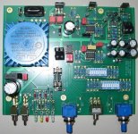
Here some images of the assembled PCB.
It will include:
PCB parts list, Part location, Schematic, Pictures, original Mark Kelly doc, Nice little FAQ's that I collected over the months I worked on the project. It should contains all the needed information to complete the project, such as PCB Test points, how to connect an external wallmart charger if you choose not to use the PCB transformer, etc...
I'll be there for any questions you may have.
Here some images of the assembled PCB.
Attachments
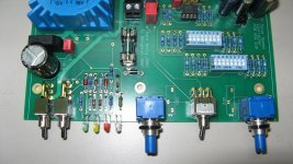
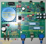
Details, showing the leds, switches, pots, etc, and some of the test points (TP).
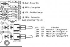
Two switches on the left are for, Motor ON (SW2)-Left SW, Charge ON (SW3)-Right SW
SW2 SW3 Function
UP UP Motor ON / Charger OFF
DN DN Motor OFF / Charger ON
UP DN Motor ON / Charger ON
DN UP Motor OFF / Charger OFF
Leds are:
BLUE: Power On, Motor is running
GRN: Battery is Ok, i-e Vbatt> 11.4V, Led start to dim for Vbatt<12V
YEL: Battery Trickle Charge. On if VCharger > 13.8V
RED: Battery Charging. On if VBatt is lower by 2V than VCharge
3 TP's, Look on the left, just over the 2 switches:
Vcc (Main PCB supply),
Charger+ (Internal Charger Volatge)
Batt+ (Battery Voltage)
Just under the blue transformer, you can see where to connect an external charger, such as a 18Vdc wallmart adapter, if you choose not to use the integrated battery charger. Points are marked " Ext. Charger" GND and V+
We see that you can install the 1Turn pot or the 25Turns trimmer but not both at the same time. Here the 1T pots are used.
Also shown are the battery fuse and reverse batt. voltage protection diode (D2) and the Switch speed selection (between both pots) and the pot range selection DIP switch, one per speed.
Attachments
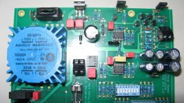
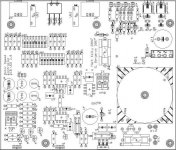
Last PCB detail picture. From left to right:
X1-L,N tab connectors, AC supply input for charger, with voltage selection jumpers 120/240V. Main power fuse F1, covered here with protective shrink, for safety. Main charger transformer (in blue). The integrated charger has the needed power to charge the battery at the IC1 programmed charge current. Once the battery if really discharge, T1 voltage drops because of current demand, reducing IC1 power dissipation. Once the battery gets charged, T1 voltage increase, and IC1 current decrease to supply only battery tricle charge. Works really well.
Two last Test points V+ (Circuit supply) and GND
Three IC and power transistors to connect to a heatsink or to some case metal part (use insulators!). They are on the side, top section.
Two external connectors X2 (Batt) and X3 (Motor). Near X3 you see the optional R24, use to increase motor current sense if needed at time of calibration, see Mark docs and my FAQ file. In the middle section you can also see the 25T trimmer use in the PCB calibration, again see Mark doc.
JP2 Header 3 pins connector to select between circuit motor current feedback, or no feedback (Reference to GND), see schematic.
Attachments
This PCB was done using cut and paste with both Mark Kelly PCB's (so in fact you're getting Mark PCB...), with the addition of my integrated charger and built-in Switches and Led indicators and a few little additions such as TP, battery fuse, etc.
Here each sections:
Here each sections:
Attachments
What a great job you have done.
The custom plates look GREAT too. What a shame i did not order one 🙁
Is there any chance to get one more?
Bye,
Boris
The custom plates look GREAT too. What a shame i did not order one 🙁
Is there any chance to get one more?
Bye,
Boris
Note on shipping:
I'll try to use surface shipping as possible because the motor has powerfull magnets and they may be declared Dangerous Good when ship by plane (as indicated on a sheet that came with the motors), so I won't take any chances...
It may also be the only shipping alternative that make any sense, price wize with the kit that includes the pod. It weight almost 1kg just by itself. Express shipping by air will be very expensive.
So, if not requested otherwise, I'll quote you surface shipping.
Also to save me endless back and forth trips to the post office, I got a small digital scale and I get my shipping cost estimate from Canada Post web site using the box weight and dimensions. These are estimates and actual shipping cost may be higher. Also, I get estimate in $CAN, you'll pay me in U$ but the exchange rate is fluctuating a lot and the U$ is almost equal to or less than the $CAN at this time.
So I may round off the cost estimate a little bit. It will be faster for me, and for you. You'll send one last payment and we will close the case.
Just to let you know, I have left two partial parts kits (semi-conductors and IC's), 1 transfo, 1 pair of 1T pots, most of the caps and resistors, except the RSA5 power resistors.
If interested, send me an email.
Bye...
If interested, send me an email.
Bye...
Ed LaFontaine shown interest in the parts kit.
Peter Daniel kit was shipped today.
I have 4 completed lines in my Group Buy. Things are starting to move.
To the ones I already contacted, please reply, so I can go ahead and ship your kit.
The controller prototype is running my Tecnodec at this very moment, using a Teres pulley. I re-charged the battery 2 times so far. Switches and Leds indicators are all working correctly. Still playing a little with the adjustments. Nice thing is we can use the controller and re-charge the battery at the same time if we like.
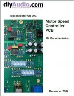
Documentation:
Peter Daniel commented on the first version of the documentation. He said it looks good.
I'll try to complete the documentation with a complete PCB schematic and some PCB assembly tips. I want also to include a schematic with actual volt/current measurements on it. There is a first version already included but they were taken with a test motor and my own PCB version.
Current version is 1.0. Ask me if you want a copy. I'll send one with each last payment at the time of shipping.
HI Sylvain,
Just to let you know that my controller is up and runing, I will send you pictures of the end unit.
Many thanks for all your help on this.
Just to let you know that my controller is up and runing, I will send you pictures of the end unit.
Many thanks for all your help on this.
Glad to hear it. You're the first to actually use this year new controller PCB with his actual setup. I'm really happy we were able to solve your problem. Please send us some comments on the final result and some good pictures 😎 I know you have a killer custom table.
Just sold my two last partial parts kits to Ed Fontaine and Keith Fitzgibbon. So no more parts. I'll still have some BD139, 140 and the small TO-92 transistors left as spare parts if you destroy some 
Time to start counting parts again...
Time to start counting parts again...

- Home
- Group Buys
- 2007 Maxon Motor Group Buy