I didn't want to open up a can of worms here...
OK, just a little comment then.
Your 6.1 picture indicates that 600 Hz is clearly in the ray acoustics area, usually considered "the speaker in control".
The 5.4 picture has it in the area of combined direct and early reflections.
The early reflections are not modal and I wouldn't say "the room is in control".
They are reflections but can be controlled by the speaker directivity.
But it's half full / half empty, more a question of interpretation so I am happy to close back the can.
Sorry...the information is spread widely in snippets and not easy to find
No problem.
The fascination was not meant to refer to your mention of it in this thread 😉
I have never mentioned the preference score in any other post or forum in my entire life until now...so ?
...overall I prefer reduced reflections or narrower directivity.
Yes, narrower directivity may help me too because I have a fairly lively sound room.
In a double brick house, concrete slab floor and internal masonry walls.
Nice thermal mass for Canberra summer days but needs heroic efforts for bass modes.
Probably membrane absorbers built into custom bookshelves and 4 subs placed to reduce modal excitation, only have 2 so far.
Best wishes
David
Last edited:
Might be, the depth setting in ATH script is something close to 300mm I think and the roundover affects the actual depth. This was just an example where I was at two days ago 🙂
Depth/length gives output gain - see ship and train horns, but I'm not so sure its the way for audio reproduction. Probably a shallower WG sounds and measures better?
//
Yes on both and that was my point, by 1K I see that good control has been asserted by the speaker but below that things get a little messier in room. The more early reflections that are absorbed or directed away the less messy things are in that region. The closer to 1k the smoother things are the further away the more things vary with position.OK, just a little comment then.
Your 6.1 picture indicates that 600 Hz is clearly in the ray acoustics area, usually considered "the speaker in control".
The 5.4 picture has it in the area of combined direct and early reflections.
At 200Hz and below where the room has asserted itself I don't think these distinctions matter so much.The early reflections are not modal and I wouldn't say "the room is in control".
They are reflections but can be controlled by the speaker directivity.
Agreed 🙂But it's half full / half empty, more a question of interpretation so I am happy to close back the can.
Neither comment was meant to refer to you. I basically do not understand why so much effort is being put into optimizing scores, particularly when you can make the score better but see from the Spin that the basics of Toole's research are being ignored in favour of the score.I have never mentioned the preference score in any other post or forum in my entire life until now...so ?
All the parameters are interactive, the depth and the coverage angle work together to set the overall width of the horn, to make the horn physically wider at the same angle means it needs to be deeper to maintain the profile.Depth/length gives output gain - see ship and train horns, but I'm not so sure its the way for audio reproduction. Probably a shallower WG sounds and measures better?
//
Once an angle and maximum acceptable width has been determined the depth sets itself. The response gets smoother from stretching the curve out and making it change more gradually, but it increases beaming. Going big on the termination parameters helps but then the size increases significantly. The right balance of smoothness, coverage and size is tricky to get without the luck of the Czech 🙂
For 15 to 20" guides with 90 degree to 120 degree coverage the depths would be in the 120mm to 220mm give or take.
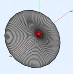
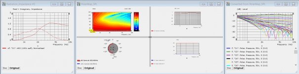
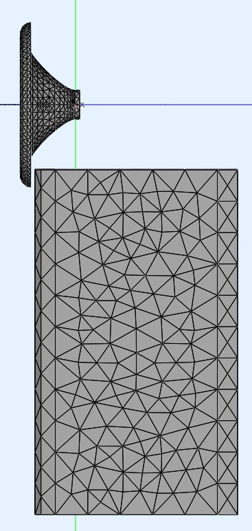
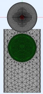
To simulate the effect of a woofer cabinet below a freestanding horn I need to mesh the horn in 3D rather than using circsym. I've hit a bit of a snag as the rollback horns are not simulating exactly the same as in circysm and the effect of the interface seems to be more significant than before. Simulating the whole thing as an exterior works with circsym but produces garbage results with a mesh. The subdomain modelling is supposed to give the same result as a single domain. It looks like a mouth reflection would in the radiation impedance and there is a ripple in the polar. Sometimes I can clean up the Radiation impedance but the polar ripple always remains even if it is suppressed.
The is the circysm result which is clean is attached below.
The is the circysm result which is clean is attached below.
Attachments
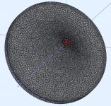
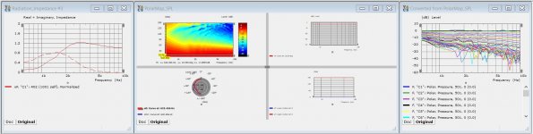
Using the interfaces from Ath selecting the last slice and offsetting the interface to clear the front gave the best results with the least ripple.
This is a high density 5mm mesh and interface, the extra density made very little difference to the result. This was on a full size guide the previous was a scaled down version for testing.
This is a high density 5mm mesh and interface, the extra density made very little difference to the result. This was on a full size guide the previous was a scaled down version for testing.
Attachments
Neither comment was meant to refer to you.
Ok, since it was in a post to me I read it differently to your intention, all clear now.
..particularly when you can make the score better but see from the Spin that the basics...
Practically any metric can be gamed, and usually is, but that is not my intention.
I just want to use the research to see how off-axis unevenness (nulls) are likely to impact the sound of the speaker and determine best trade-offs.
But your comment has made me curious- I half joked in another thread that it would be possible to game the Spinorama.
However I haven't actually seen any examples where the speaker has been made to score better at the expense of visible anomalies in the Spin'.
Where can I see this?
I finally have had a close look at the Sean Olive Preference Score paper.
Some serious work there but doesn't look totally solid statistically.
He is open about some problems in the work, and there are others he doesn't mention that don't look quite correct to me.
So it seems particularly ill advised to compromise the Spin' to improve a metric that is still debatable.
There is an extended thread about this on ASR that I need to plow thru.
Best wishes
David
Nice work on the consistency check between circsym and fully meshed.
Last edited:
I just want to use the research to see how off-axis unevenness (nulls) are likely to impact the sound of the speaker and determine best trade-offs.
But your comment has made me curious- I half joked in another thread that it would be possible to game the Spinorama.
However I haven't actually seen any examples where the speaker has been made to score better at the expense of visible anomalies in the Spin'.
Where can I see this?
Off axis nulls seem to be much less of an issue in all of the preference research I have read. They can be quite significant and not noticed. Off axis peaks or resonances as Toole terms them are much more of an issue.
It was in one of the ASR threads where EQing the NFS measurements was discussed.
Optimising the SM_PIR, the smoothness of the predicted in room result gives a better score in most cases, however it can be seen that doing that changes the on axis and listening window in a negative way in some speakers. I view the on axis and listening window as the main target to be improved moving then to a smooth off axis response. EQ'ing the PIR goes against the idea that the best in room result comes from a flat on axis sound with smooth directivity. Going about it the other way is like EQ'ing speakers in room to a target without knowing their directivity. It can work but the target will be different for each speaker to get the same perceived response.
Thanks, I just wish I could get them to be the same 🙂Nice work on the consistency check between circsym and fully meshed.
For anyone following along who might want to give this a go themselves I found a couple of good videos today on the use of the new Akabak version that I thought helped explain things well.
Simulating Waveguides in Akabak - YouTube
AKABAK - Videos
Simulating Waveguides in Akabak - YouTube
AKABAK - Videos
Off axis nulls seem to be much less of an issue in all of the preference research I have read.
That is what I understand too.
Now that I think about it I don't recall that the Olive Preference score makes any distinction between peaks and dips in the calculation of "smoothness".
So perhaps less useful than I expected.
Off axis peaks or resonances as Toole terms them
Not so much a matter of terms, rather an observation that consistent peaks usually are caused by resonances.
Physically different cause to that of cancellation dips and probably perceived differently.
...the SM_PIR, the smoothness of the predicted in room result
Olive calls SM_sub "smoothness" but that's not actually what it is, apparently.
I initially took it at face value, just a faint idea that it should be checked.
But I plowed thru the ASR thread and found I wasn't the only one with doubts.
Have to reread the posts to make sure they have it correct themselves but it looks like a misnomer.
This adds further issues to the Olive metric.
But I take your point, whatever the term.
... the idea that the best in room result comes from a flat on axis sound with smooth directivity.
Yes, I want flat on axis and smooth directivity too, of course.
That's just the flip side of my point, the nulls mess up the directivity so it isn't so smooth.
Why is this so difficult, inconsistencies in ABEC, flaws in the speaker measurement standard, mistakes in the Klippel software, weakness in the preference metric, and speakers that just don't want to be flat and smooth?!
Best wishes
David
Within the listening window the dips from a vertically aligned crossover can be quite mild and that is the part that matters most to me, outside of that things can get much worse in a narrow band without being heard the way it looks to the eye. Keeping the overall directivity and response from the waveguide smooth and matching the directivity of the woofer through waveguide and cabinet shape should help to make the overall trend as smooth as possible and free of peaks. Dips at crossover deepening off axis being the only blemish.Yes, I want flat on axis and smooth directivity too, of course.
That's just the flip side of my point, the nulls mess up the directivity so it isn't so smooth.
Why is this so difficult, inconsistencies in ABEC, flaws in the speaker measurement standard, mistakes in the Klippel software, weakness in the preference metric, and speakers that just don't want to be flat and smooth?!
This is my overall aim for this speaker anyway 🙂
The steeper crossover minimizes the frequency range where the drivers interact, crossing steeper to move the crossover point lower can help too. I can run some Vituix sims to show the difference.
Yesterday I thought I would start playing with Akabak, the videos I posted links to before gave me confidence that I could click my way through it all given that I know what I want to do.
It was easy enough and I soon had something ready to go. I wanted to try and use Fusion to generate the profile and interface so that I could use a different junction and enclose more of the air around the rollback in the interior domain.
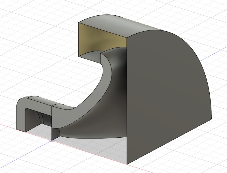
I tried Gmsh 4.7.1 which has the curvature options mentioned in one of the videos. It didn't make much difference on an Ath guide. It still used too few triangles at the throat. I resorted to brute force and ran the whole thing at 5mm resolution. That came out to 6500 elements and took 10 hours to solve 😱
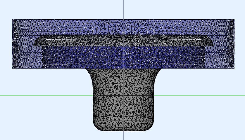
In hindsight that was not the first sim that I should have run with Akabak but it did solve and produce good results so I got away with it 🙂 It did reduce the ripple a little more from the previous attempt but with way too much solve time for it to be useful. Results attached below Top line is ABEC with the Halo and bottom is Akabak with Fusion Interface.
It was easy enough and I soon had something ready to go. I wanted to try and use Fusion to generate the profile and interface so that I could use a different junction and enclose more of the air around the rollback in the interior domain.
I tried Gmsh 4.7.1 which has the curvature options mentioned in one of the videos. It didn't make much difference on an Ath guide. It still used too few triangles at the throat. I resorted to brute force and ran the whole thing at 5mm resolution. That came out to 6500 elements and took 10 hours to solve 😱
In hindsight that was not the first sim that I should have run with Akabak but it did solve and produce good results so I got away with it 🙂 It did reduce the ripple a little more from the previous attempt but with way too much solve time for it to be useful. Results attached below Top line is ABEC with the Halo and bottom is Akabak with Fusion Interface.
Attachments
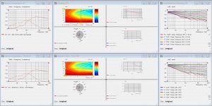
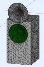
Now for a result that I find quite exciting. What happens to a freestanding guide when you put a woofer box underneath it. The good news is not much 🙂 No real effort was made to make the box super low diffraction. This is the same size woofer and waveguide as in the previous cabinet simulations. It seems you can put the guide in front of the box very close to the woofer and have a good result. This to me seems like a good option. I can also see some aesthetic design options here too.

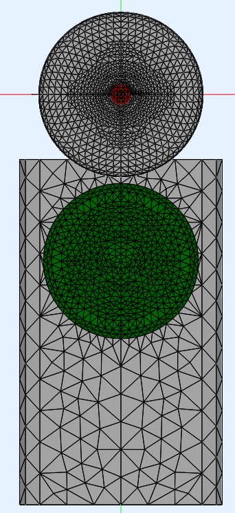
Comparison results attached below, top line is with woofer cabinet, bottom is without. Something weird happens to the radiation impedance high up but otherwise seems normal.
Comparison results attached below, top line is with woofer cabinet, bottom is without. Something weird happens to the radiation impedance high up but otherwise seems normal.
Attachments


Last edited:
These are very promising results! I'm working on a similar project, and it's exciting to see these graphs, as nice as they are. Looks like there's room for a ton of flexibility with the woofer cabinet design, which is awesome.
- Home
- Loudspeakers
- Multi-Way
- 2 way waveguide speaker build ABEC modelling