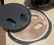
DAS M50 converted from screw on to flange mount. Using a 3D printer and two M6 hex head screw.


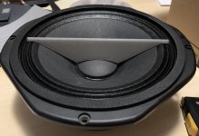
The LF driver will be most probably Fane Sovereign 8-225, which worked really fine not only in this design, but also in the "Kallax" MEH I built. The Pro version is only slightly more expensive. It offers a cast basket, push terminals and better controlled FR.


My only concern is that the datasheet of the Pro version says that rear mounting is N/A. Is there any problem I could expect with this style of basket when mounting from the rear on the horn? If not, I will go for the Pro version.
My only concern is that the datasheet of the Pro version says that rear mounting is N/A. Is there any problem I could expect with this style of basket when mounting from the rear on the horn? If not, I will go for the Pro version.
You could make a mounting ring with a recess for the driver flange, bolt the driver into the ring from the front.
Then screw / bolt the ring to the horn wall.
Rob.
Then screw / bolt the ring to the horn wall.
Rob.
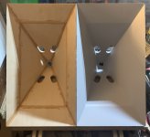
Meanwhile I tried to design a cone filler with ports - to see if I can get higher than without it.

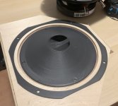
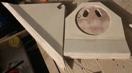
The devil is in the details. It turned out slightly wider than it was supposed to be. It is quite nicely square, but the fit is far from perfect - but it will work.
I will try to 3D print a jig for better glue up.

I will try to 3D print a jig for better glue up.
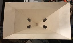
So the 3D printed jig worked quite well...not perfectly, it would need some more tuning and I was not patient enough. It was much easier and quicker to glue all 4 sides at once, but I overtightened the clamps a bit and had a bit of slide on the side panels. The first one ended up being ca 2 mm wider, the second one is ca 2 mm narrower than the 3D model. So before building the box around them, I will have to build a small frame around to compensate for the difference. And also lots of putty goes to the gaps.
In the end, I am pretty happy at least the front is square. The first one made from MDF was far from square. If I ever build another pair, it will be even better🙂
In the end, I am pretty happy at least the front is square. The first one made from MDF was far from square. If I ever build another pair, it will be even better🙂
Attachments
So since you moved on from the 4 (3inchs or 4 inches) do you think you will get better results?
I expect/need more low end in a relatively small box. The large ones (https://www.diyaudio.com/community/...s-pt2522-tweeter-faitalpro-3fe22-mids.400527/) will still be three way.
I have heard these built by @Johannes619 and that is why I revisited them and am building a pair for myself. The "Kallax" MEH is ok, these will have more low end and SPL and will still fit into the limited space I have.
I have heard these built by @Johannes619 and that is why I revisited them and am building a pair for myself. The "Kallax" MEH is ok, these will have more low end and SPL and will still fit into the limited space I have.
copy i thought these would still sit above the para-flex kick you had which is why i asked. I think an interesting design can be had with the combination both..
Definitely, Johannes619 is using them with kicks and subs (he might provide more detail on them), my pair will be for home use with less max SPL - only with a mono subwoofer.
Having a pair of these with one kick and two subs per side makes a pretty nice PA.
Having a pair of these with one kick and two subs per side makes a pretty nice PA.
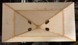
I have used my accumulator powered electric planer for the first time. What a wonderful (and dangerous) tool it is. I planed down the wider horn sides in a few minuter, so both will be the same width. I learned the hard way to make one pass and measure. The wider horn will be asymmetrical by a millimeter or two and I had to plane down the sides of the narrower horn as well.
But now the mission is accomplished and both will fit into a box of identical dimensions without making a special frame around each horn.
But now the mission is accomplished and both will fit into a box of identical dimensions without making a special frame around each horn.
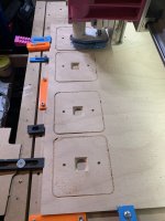
Work in progress🙂 Cutting parts for the box on the CNC. Tomorrow, I should have all parts for one box done. Sides will be 18 mm including access doors, top, bottom and back will be 12 mm. Just using what I have at hand, no other reason for that. The back will have 200 x 200 VESA mounting points so that the boxes can be mounted on a extendable TV holder.
Attachments
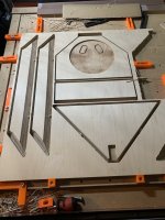
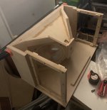
Some more progress today. Bottom, horn and sides including the access panels. Tested that they are large enough for comfortable manipulation inside.
Since I am cutting the rectangular panels on a CNC, I started to appreciate the drawing functions of CamBam. Panels like these can be drawn and have gcode produced in a very short time. I have all the parts cut with the exception of 4 18 mm braces for the Vesa mount - to hold the T-nuts in place.
Since I am cutting the rectangular panels on a CNC, I started to appreciate the drawing functions of CamBam. Panels like these can be drawn and have gcode produced in a very short time. I have all the parts cut with the exception of 4 18 mm braces for the Vesa mount - to hold the T-nuts in place.
Attachments
Last edited:
- Home
- Loudspeakers
- Multi-Way
- 2 way Synergy inspired by SPL Runt