You'll need to do more tweaking, by the way. Just moving the XO to 2 kHz wasn't going to be enough. 🙂 I'm deliberately letting you play. It's not entirely an easy thing to fix either. My suggestion now is save new versions of your XO often. 🙂
Best,
Erik
Best,
Erik
Haha, thanks for letting me rip out my hair here 😉You'll need to do more tweaking, by the way. Just moving the XO to 2 kHz wasn't going to be enough. 🙂 I'm deliberately letting you play. It's not entirely an easy thing to fix either. My suggestion now is save new versions of your XO often. 🙂
I thought i had something going here with a Xover point of 2kHz and what i thought was decent phase alignment but when i invert the tweeter its far from the clear null i was expecting 😕
Attachments
Last edited:
After thinking about it, I think your phase plot for the tweeter is probably wrong. It's way too steep.
Can you post the raw drivers, with phase?
Nothing else.
Best,
Erik
Can you post the raw drivers, with phase?
Nothing else.
Best,
Erik
The woofer looks right, but I'm having trouble with the tweeter. I'm not used to seeing a tweeter wrap around 180 that many times. Could you please remeasure it and see if you get the same results? Try at 1V or so, so you don't break anything, without any crossover at all.
Best,
Erik
Best,
Erik
I didn't do any further measurements on the tweeter tonight but instead i tried to find other phase measurements on the internet to use as a reference 🙂
I found this:
faktiskt.se • Visa tråd - EPS - den ultimata nybörjar diy-h-talaren! (Mycket bilder!!)
CT62 - 0 degree, 50cm:

Apart from the big rather strange dip he measured in the first slope its quite similar?
I found this:
faktiskt.se • Visa tråd - EPS - den ultimata nybörjar diy-h-talaren! (Mycket bilder!!)
CT62 - 0 degree, 50cm:
Apart from the big rather strange dip he measured in the first slope its quite similar?
Attachments
Last edited:
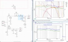
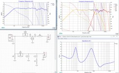
Im finally getting somewhere!!! 😀
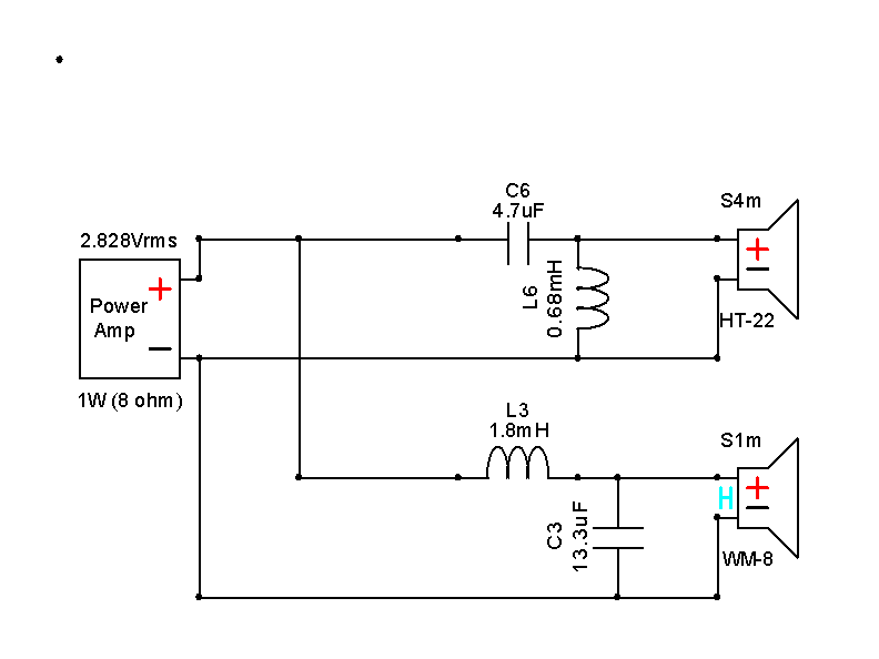
I found this tweeter circuit while looking for the tweeter curve above:
Philips 9710/
Im getting an awesome phase alignment here together with a decent flat FR.

Inverted tweeter:

Any tips in how to get rid of the dip in 4-5kHz? I know it may be to flat but this is by far the best ive seen regarding the phase! 😀
I found this tweeter circuit while looking for the tweeter curve above:
Philips 9710/
Im getting an awesome phase alignment here together with a decent flat FR.
Inverted tweeter:
Any tips in how to get rid of the dip in 4-5kHz? I know it may be to flat but this is by far the best ive seen regarding the phase! 😀
Attachments
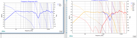
The FR is similar, the phase is not! 🙂 Very odd!
You seem to have an extra 180 degree crossing and that's making the clarity I'd have expected off. Look at the image from the web. Notice it crosses around 1,500 and 9,000 Hz. Your measurements seem to throw in a third crossing in between, or am I misreading?
Best,
Erik
You seem to have an extra 180 degree crossing and that's making the clarity I'd have expected off. Look at the image from the web. Notice it crosses around 1,500 and 9,000 Hz. Your measurements seem to throw in a third crossing in between, or am I misreading?
Best,
Erik
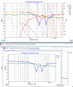
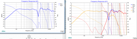
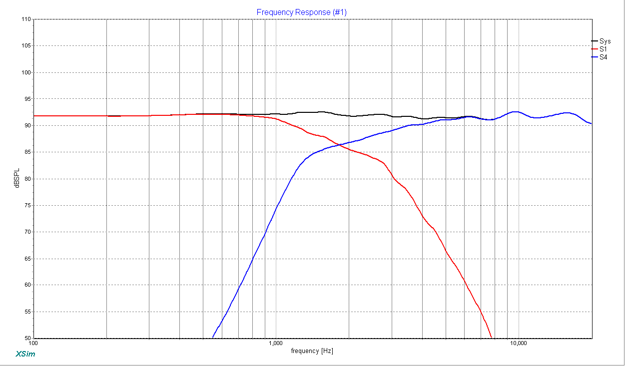
Its getting late but its getting better 😛


I think the null im getting here is the clearest one yet, its not interfering with anything before or after the with of the null.
I think the null im getting here is the clearest one yet, its not interfering with anything before or after the with of the null.
Attachments
Sultanen, maybe I'm being a bit dim here, but I've really no idea what this speaker is! 😀Its getting late but its getting better 😛
I think the null im getting here is the clearest one yet, its not interfering with anything before or after the with of the null.
Could you review what drivers and box you are using?
Ye, its kinda odd right =)The FR is similar, the phase is not! 🙂 Very odd!
You seem to have an extra 180 degree crossing and that's making the clarity I'd have expected off. Look at the image from the web. Notice it crosses around 1,500 and 9,000 Hz. Your measurements seem to throw in a third crossing in between, or am I misreading?
The one from the web has crossings at 1.5, 9 and 18kHz
Mine has the crossings at 1.8, 9 and 15kHz with a last one that probably crossing at like 22kHz. The web one has started this last one as well but its crossing alot later and is cut of at +30degree where mine is cut of at -150degree.
I dont know if this makes much of a difference though? Im getting great phase alignments with the new tweeter circuit. Alot easier to get it it to align now 🙂
Welcome back here 🙂Sultanen, maybe I'm being a bit dim here, but I've really no idea what this speaker is! 😀
Could you review what drivers and box you are using?
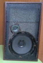
Its a speaker from deep deep down in the flames of doom 😀
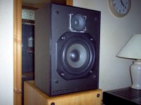
The box:
ITT 4015
Measurements: H 35,0 - B 21,0 - D 22,0 cm
Volume: 8,6 liter
Weight 4,3 kg
Tweeter:
Peerless CT62
http://spicaspeakers.com/pdfs/peerless-801730.pdf
Woofer:
Peerless 833429 WF165 (6.5")
fs= 4.57000000000000E+0001
Vas= 2.07000000000000E-0002
bl= 7.50000000000000E+0000
ss= 1.30000000000000E-0002
Qts= 3.50000000000000E-0001
Re= 6.10000000000000E+0000
Le= 8.00000000000000E-0004
LeLoss= 6.50000000000000E-0001
dmax= 4.00000000000000E-0003
pmax= 1.50000000000000E+0002
And my goal now is to get an really awesome badass crossover to go with it 😀 😉
Last edited:
I'm still a bit confused here. This doesn't look like your original posting.
The ITT 4015 employed a SEAS woofer which Troels Gravesen called a Blackcone along with a similar cone tweeter.
http://www.troelsgravesen.dk/blackcones.htm
I'm not sure if we are talking about a 6" or 8" bass. Different animals. But the idea was the SEAS had high Qms, albeit with puny bass, so was quite dynamic.
But not hard, IMO.
Attachments
Ye, its kinda odd right =)
The one from the web has crossings at 1.5, 9 and 18kHz
Mine has the crossings at 1.8, 9 and 15kHz with a last one that probably crossing at like 22kHz. The web one has started this last one as well but its crossing alot later and is cut of at +30degree where mine is cut of at -150degree.
I dont know if this makes much of a difference though? Im getting great phase alignments with the new tweeter circuit. Alot easier to get it it to align now 🙂
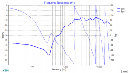
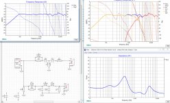
I was going to suggest you are ready, but I just saw your latest impedance plots. 2 Ohms is way too low!
You'll need to prevent that, probably by adding some 1 or 2 Ohms to the caps in the woofer section and/or L2.
Erik
Last edited:
I understand your confusion 🙂 This is quite a long thread and its impossible to read all of it.I'm still a bit confused here. This doesn't look like your original posting.
The ITT 4015 employed a SEAS woofer which Troels Gravesen called a Blackcone along with a similar cone tweeter.
BLACKCONES
I'm not sure if we are talking about a 6" or 8" bass. Different animals. But the idea was the SEAS had high Qms, albeit with puny bass, so was quite dynamic.
But not hard, IMO.
The box is as a ITT 4015 BUT the drivers are both changed, the tweeter is a Peerless CT62 and the woofer is a Peerless 833429 6.5inch element.
I guess you are also confused by the initial curves that are VERRY different from what im using now? The thing is that the initial measurements was way off. Since then i have changed a number of things:
- Built a new microphone based on WM61A.
- Built a mic pre-amp based on John Conover: Using the Panasonic WM61A as a Measurement Microphone Fig VI.
- Built an impedance measurement box.
- Changed to ARTA for FR+impedance measurements
- Changed to impulse measurements.
- Introduced the concept of nearfield measurements and merged the woofer nearfield and farfield with the Excel sheet "FRD Response Blender 2.0.xls", also added a calculated baffle step correction in that sheet.
Something like that, is it more clear? 🙂
Thanks for that, i actually noticed that after posting the data 🙂 I will try to correct this during the day! I did one further change and added a notch to the tweeter to eliminate the last bump around 7kHz 🙂 It's awesome, i think i finally grasp this quite well now 😀I was going to suggest you are ready, but I just saw your latest impedance plots. 2 Ohms is way too low!
You'll need to prevent that, probably by adding some 1 or 2 Ohms to the caps in the woofer section and/or L2.
Erik
Thanks for letting me fool around with the simulations myself, its actually a really good lesson!😀
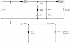
If were getting close to the goal now, would you say that there is some component sizes in the latest circuit that are way off or unrealistic?
I had one thought on Coils, is this level a decent one? 0.7ohm in 2.7mH. If you go lower than this its getting quite expensive 😛
http://www.audiohobby.eu/en/jantzen...-air-core-coil-27mh-awg17-07ohm-000-1041.html
Last edited:
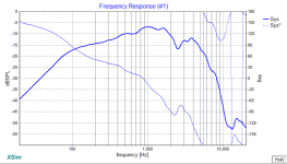
For the woofer 0.7 seems a little high, but you can model this in XSim. 🙂 The Jantzen P-Core coils are pretty good compromises of low impedance and price.
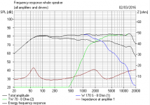
Don't worry too much right now, let's finish voicing the speaker. It's a little too flat, and needs to point downwards a little more, especially since you are using far-field measurements.
Take a look at the earlier example I sent you. Export the final FR from that and import it into your current xover. That will give you a good reference point.
Best,
Erik
It seems in Europe the P Core inductor comes in a lot of different gauges. This is a good compromise:
Jantzen Iron Core Coil with Discs 2,700mH AWG17 0,227Ohm, 000-5476 - Fidelity Components Shop
but it seems that you can go up or down gauges. Via Parts Express here we only get one. 🙂
Best,
Erik
Jantzen Iron Core Coil with Discs 2,700mH AWG17 0,227Ohm, 000-5476 - Fidelity Components Shop
but it seems that you can go up or down gauges. Via Parts Express here we only get one. 🙂
Best,
Erik
I'll try and help a bit here. 6" bass is IMO, a tough speaker to get sounding good. But I have an idea.
Let's use Marco_Gea's shallow 2nd. order tweeter filter:
Obviously a totally different bass filter. I think the below third-order bass Heybrook HB2 ideas might tie it all together. Lastly my trial cabinet for 6" bass.
Let's use Marco_Gea's shallow 2nd. order tweeter filter:
Obviously a totally different bass filter. I think the below third-order bass Heybrook HB2 ideas might tie it all together. Lastly my trial cabinet for 6" bass.
Attachments

- Status
- Not open for further replies.
- Home
- Loudspeakers
- Multi-Way
- 2 Way speakers - Suggestions on improvements?