Length value is axial length (on whichever CAD axis represents depth) Height/2 and Width/2 represent half the value of the height and width dimension needed to make a square or rectangle that equates to the area. Effectively you will make a bunch of different sized squares (for equal height and width), one every 0.2cm along the length. Whether you need that many to accurately describe the shape depends on what it is.Can anyone help me understand how to create the CAD diagram using this file?

By thin you mean the shape, or thickness? (The image below was posted in post #16)
Although the adaptor was a tight fit It is difficult to confirm leakage. Once we have the new adaptor at hand I'll look at this region specifically.
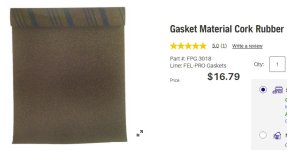
I use Fel-Pro 3018 to make gaskets if I want to make sure there's a good seal. The rubber-cork is easy to cut, seals well and conforms to imperfections without sticking to surfaces. It's available at most automotive supply stores, and there's probably a local brand you could use.
Attachments
Do I understand correctly that you have resonances even after fiberglass + POP? If yes, how have they been evident (measurement?)?
While waiting for some filaments I have ordered, I believe (intuitively) that wood or flexible fibers would have the highest internal damping. But perhaps printing with a cavity with very little infill and pouring resin or something else, like mbat has shown in his thread, is the most effective way and helps in the build too.
Rap test. It did not sound inert enough. I also dislike the surface. It does not feel homogeneous. A resin print might yield a smoother surface, and perhaps you'll have more success with the damping. Keep us posted.
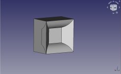
A test sample of the ring to see if it fits perfectly before we print the whole adaptor.


So I was just trying to change the design of the bass cabinet front horn using hornredp from axisymmetric to rectangular and see how it looks like.
I generated the hornredp schematic file attached with this post.
Now I am confused about how to translate it into a CAD diagram.
Can anyone help me understand how to create the CAD diagram using this file?
The wall curve profiles can be previewed in Hornresp.
If a 3D view/model is needed I create 2 sketches and extrude them. The conic is a straight line so only 2 points are needed. The curved wall sketch uses control points for a b-spline. Even 1cm resolution is sufficient to get a good smooth curve (8 points used in this pic). It's better to have the curved wall in the horizontal but this is how the text file spec'd it.
Attachments
I have gasket tape. I shall try this with the new adaptor.I use Fel-Pro 3018 to make gaskets if I want to make sure there's a good seal. The rubber-cork is easy to cut, seals well and conforms to imperfections without sticking to surfaces. It's available at most automotive supply stores, and there's probably a local brand you could use.
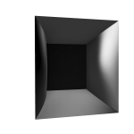
So I drew the picture of the bass horn somehow using tips from @fluid & @DonVK 😀
It looks like this (curved walls controlling horizontal dispersion and straight conical walls controlling vertical dispersion):

Now I have another doubt. some part of the driver close to the surround will be covered by the inlet of the above horn.
For example, to show what I mean, I took a pic from an old ALTEC system and have shown below. In it a part of the driver is covered by the horn at the sides.
what is that covered part of the driver facing? is it a rigid wall? Or the wooden horn touches the driver frame?
If the horn frame doesn't touch the driver frame, how much space should we leave between the two? (if the covered part of the driver is indeed facing a rigid wall, wouldn't some reflections from that wall hit the driver back)

I got some of these doubts seeing some pics from build by Joseph Crowe here:
https://josephcrowe.com/products/speaker-system-no-2087


It looks like this (curved walls controlling horizontal dispersion and straight conical walls controlling vertical dispersion):
Now I have another doubt. some part of the driver close to the surround will be covered by the inlet of the above horn.
For example, to show what I mean, I took a pic from an old ALTEC system and have shown below. In it a part of the driver is covered by the horn at the sides.
what is that covered part of the driver facing? is it a rigid wall? Or the wooden horn touches the driver frame?
If the horn frame doesn't touch the driver frame, how much space should we leave between the two? (if the covered part of the driver is indeed facing a rigid wall, wouldn't some reflections from that wall hit the driver back)
I got some of these doubts seeing some pics from build by Joseph Crowe here:
https://josephcrowe.com/products/speaker-system-no-2087
Attachments
It is not unusual for the driver to be covered either a little or a lot by the horn in front of it.
You can see some images of a Pi 6 build here
https://www.diyaudio.com/community/...-seven-pi-speakers-spring-summer-2021.378045/
In that case there is no relief in the mounting plate to allow for suspension movement, for a woofer that would not work as well as they are likely to move if producing low frequencies. A ring can be routed to allow for suspension movement so the surround does not contact the plate.
There is some compression formed when the driver is covered, taking this further it then becomes a band pass enclosure like the drivers in a Multiple Entry Horn. Reflection and diffraction from the cone and horn is relative to wavelength.
@vineethkumar01 The example that I provided was only to illustrate the benefit of a short horn. The throat area (S1) was set to the Sd out of convenience and not a requirement. I made some guesstimates based on the VCAD files. "Sd" is always smaller than the physical driver, and there was no intention to restrict the woofer (compression). Compression will increase output SPL, but at a cost of decreased bandwidth (ie. acts like a low pass).
In Hornresp, adjust S1 area to the physical woofer rectangle size to prevent compression. The depth or mouth size may have to be changed as well, since they are all interdependent. If the size or bandwidth or anything else does not suite your needs then we can change it. Many design tradeoffs will depend on what you want. I'm more than willing to help drive Hornresp to suite your needs, just don't feel obliged to build the example horn.
In Hornresp, adjust S1 area to the physical woofer rectangle size to prevent compression. The depth or mouth size may have to be changed as well, since they are all interdependent. If the size or bandwidth or anything else does not suite your needs then we can change it. Many design tradeoffs will depend on what you want. I'm more than willing to help drive Hornresp to suite your needs, just don't feel obliged to build the example horn.
I did a simulation with increased area at the mouth of the bass horn. Here is the bass reflex bass cabinet parameters in VituixCAD

The following were the input parameters to hornresp:

Got a combined response like below:

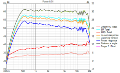
I looked at the directivity index 15 degrees off axis and it looks like this:

Seems like at about 600 Hz (for an intended corssover with the mk3b2), the DI is about 8.2 dB
The horn DI looks like below (based only on +/- 90degrees horizontal polar measurements in 5 degree steps)

The DI around 600Hz is about 6dB. Since it is supposed to go slightly higher if vertical measurements are included, will this configuration help in a reflectivity matched transition between the bass horn & woofer?
Just for additional info, here are the normalized polars (with 15degrees off axis as reference axis) of the horn

And here is the directivity beamwidth of the bass horn

Please let me know your comments about this design and suggestions/alternatives.
One thing I took into account now is that only the woofer's surround area is now covered by the horn based on below dimensions

The following were the input parameters to hornresp:
Got a combined response like below:
I looked at the directivity index 15 degrees off axis and it looks like this:
Seems like at about 600 Hz (for an intended corssover with the mk3b2), the DI is about 8.2 dB
The horn DI looks like below (based only on +/- 90degrees horizontal polar measurements in 5 degree steps)
The DI around 600Hz is about 6dB. Since it is supposed to go slightly higher if vertical measurements are included, will this configuration help in a reflectivity matched transition between the bass horn & woofer?
Just for additional info, here are the normalized polars (with 15degrees off axis as reference axis) of the horn
And here is the directivity beamwidth of the bass horn
Please let me know your comments about this design and suggestions/alternatives.
One thing I took into account now is that only the woofer's surround area is now covered by the horn based on below dimensions
I suppose that you're going to pack this up and make it into a new adapter with some of the damping techniques shown earlier?
Wrap it in plaster bandage, stick and seal the horn end with hot glue. Should be alright for one- time measurements.
Some missing links have been added to the article for download:
https://sphericalhorns.net/2023/04/09/the-mk3b2-radial-fin-horn/
New is a recommended adapter package for 1in4 and 2in0 drivers attached to mk3b2. Thanks to @DonVK who helped to prepare the simulations. We found that a slightly different T value should be used for adapters as the surface area calculation is different for adapter and horn.
So @WetFartz did measurements with the new ring adaptor 😀
Here are the 0 degrees to 180 (not 0 to 90) degrees horizontal polar measurements of the HF146 on mk3b2 in all its gory details (the measurements beyond 100 degrees seem to be corrupted by reflections though) 🙂

Impedance measurement comparison of HF146 on horn, HF146 with ring adaptor without horn, and HF146 with ring adaptor on horn

Now what is possible in VituixCAD without EQ

WIth the following EQ


Normalized directivity comparison with & without ring insert into throat
Without ring insert

With ring insert

Here are the 0 degrees to 180 (not 0 to 90) degrees horizontal polar measurements of the HF146 on mk3b2 in all its gory details (the measurements beyond 100 degrees seem to be corrupted by reflections though) 🙂
Impedance measurement comparison of HF146 on horn, HF146 with ring adaptor without horn, and HF146 with ring adaptor on horn
Now what is possible in VituixCAD without EQ
WIth the following EQ
Normalized directivity comparison with & without ring insert into throat
Without ring insert
With ring insert
Attachments
Thank you again @vineethkumar01 and @WetFartz for your tremendous effort you put into this project!
On the first view the driver exit inlay seem to do some things right/better especially beyond 10k. The fr is more even overall. I am still thinking about what contributed to this result. Besides the different opening angle and maybe reduced exit surface area it seems from the photos that the outer 4th slit is partially covered by the inlay or at least the path way is changed. Not sure how much of the outer slit is still part of the wave front.
It is obvious that it is not easy for the designer to get all slits/channels to combine coherently over the whole passband of the driver. So a very interesting measurement would be to simply cover the outer slit with some material like "Blu Tack" and do a single shot how it changes the on-axis result of the driver with the native opening section but the 4th outer slit covered.
@vineethkumar01 , @WetFartz Were the last measurements done using the "ring + old adapter" or "ring + new adapter" ?
- Home
- Loudspeakers
- Multi-Way
- 2-way horn system based on the MK3B2