
Many thanks for the photo. I can imagine how difficult it was to assemble the PLA parts especially for the throat region with the fins inmcluded. Congrats for the nice work.
But the fins are not as sharp as a knife as it maybe would have been possible using metal or hard wood. The fins are also quite thin especially at this side to the driver. But again, nice work with this material!
By looking at the frame around the throat region. Are you sure that there was no leakage?
By thin you mean the shape, or thickness? (The image below was posted in post #16)

Although the adaptor was a tight fit It is difficult to confirm leakage. Once we have the new adaptor at hand I'll look at this region specifically.
Although the adaptor was a tight fit It is difficult to confirm leakage. Once we have the new adaptor at hand I'll look at this region specifically.
If the peak frequency changes much with angle then this kind of notch doesn't really work. Often the main break up peak is consistent but not always. It looks as if the mk3b2 is already damping that region down and may not be a good candidate for it to be helpful.Thanks @fluid
I had made the reference axis as 15 degree off-axis for EQ design.
With that, this is the impact of the above filter on different responses.
So, what is the idea with the adaptor with the insert into the driver throat.
Is it that if there is a larger diameter driver (still with no big break ups till about 20kHz) and its high frequency extension is just limited by the mass roll off at the high frequency, we can somehow compensate for that mass roll off by reducing the dimension of the throat?
Is it that if there is a larger diameter driver (still with no big break ups till about 20kHz) and its high frequency extension is just limited by the mass roll off at the high frequency, we can somehow compensate for that mass roll off by reducing the dimension of the throat?
The idea is that the more gradual is the contour progression, the less reflection/diffraction there is. But it may be difficult to impossible to add a completely smooth continuation to an existing horn - it may not be possible to continue with the native contour through the adapter. In your case it would mainly eliminate the sharp discontinuities given by the wide exit angle of your driver(s). That should be a good thing in any case but how much it will improve the overall performance needs to be tried.
It's not reducing the dimension of the throat, that's a wrong way how to look at it. It's just a replacement of an existing wall contour (the conical part inside the driver) by a different one, creating a smooth whole with the horn - that's the basic idea. But for that you would have to design both parts, the inside and the outside of the driver, as one smooth curve. In your case you can only eliminate the biggest discontinutities and hope for an improvement (matching average/nominal area expansions is still not good enough). Could still be well worth it.we can somehow compensate for that mass roll off by reducing the dimension of the throat?
Last edited:
The square throat size at the main horn's entrance sets something of a hard limit in terms of the upper end dispersion charateristics. Using a smaller driver with a longer adapter does not move this very much, so I wouldn't expect making the adapter throat smaller to do much just from the size. Exponential and Hypex horns with slow opening match impedance better between the driver and air, making this slow transition start right at the phase plug exit will minimize the impedance mismatch that a fast opening conical section adds in the same way it will avoid diffraction from the change in curvature. I think this should be seen as the major advantage. It remains to be seen if this matters that much with this horn in practice. Matching the exit angle to reduce impedance mismatch has produced benefits with similar sorts of horn's. before The comparative measurements between the Faital and SB driver didn't seem to show as much of a difference as I thought they might. Worth a try for sure but too much expectation would likely lead to dissappointment.So, what is the idea with the adaptor with the insert into the driver throat.
Is it that if there is a larger diameter driver (still with no big break ups till about 20kHz) and its high frequency extension is just limited by the mass roll off at the high frequency, we can somehow compensate for that mass roll off by reducing the dimension of the throat?
Shouldn't the fins overcome this limitation? What's the point of having them there if not this? I thought that's the supposed function (well, at least horizontally).The square throat size at the main horn's entrance sets something of a hard limit in terms of the upper end dispersion charateristics.
Yea, that's just a different formulation of the same thing.... making this slow transition start right at the phase plug exit will minimize the impedance mismatch that a fast opening conical section adds in the same way it will avoid diffraction from the change in curvature.
Last edited:
@WetFartz, @vineethkumar01, if you're still eager to continue in your adventure after this exercise, you could try this one as well, it could be an interesting comparison: https://www.diyaudio.com/community/...-design-the-easy-way-ath4.338806/post-7132867
I believe I could still find the plans somewhere. (It's made of a 3d-printed adapter and bended boards.)
Could be scaled to fit the 1" phase plug exit e.g. of the HF146.

I believe I could still find the plans somewhere. (It's made of a 3d-printed adapter and bended boards.)
Could be scaled to fit the 1" phase plug exit e.g. of the HF146.
Last edited:
@David McBean so power uses area (solid angle 2D, Steridians) vs pressure on beamwidth (1D, angle) ?
[edit] updated question after thinking about it, makes sense to differentiate solid angle and beamwidth
Hi Don,
Not sure if there is still a question in there for me to answer, but perhaps the following may be of some interest 🙂.
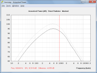
Attachment 1 compares the power response of a loudspeaker radiating into half space or a solid angle of 2 Pi steradians (grey trace), to the power response of the same loudspeaker radiating into free space or 4 Pi steradians (black trace). This example shows that power response is dependent on solid radiation angle.
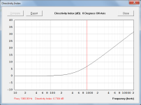
Attachment 2 shows the on-axis directivity index of the same loudspeaker radiating into free space. At 1000 Hz the gain due to the narrowing beamwidth is 6.7364 dB.
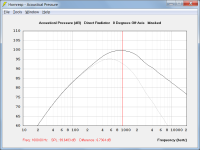
Attachment 3 compares the above free space power response (but now a grey trace) to the free space pressure response (black trace). In this case the pressure response is equal to the power response plus directivity index. This example shows that pressure response is dependent on directivity beamwidth.
Google 'power response vs pressure response' if you would like more information...
Kind regards,
David
Attachments
The combination of the fins and the size of the throat at their entry point sets a limit, making the aperture smaller before that point doesn't have as much effect as it would if the fins were at the smaller entrance point.Shouldn't the fins overcome this limitation?
Two slightly different effects that stem from the same cause.Yea, that's just a different formulation of the same thing.
It can have an effect on how much is the arriving wavefront distorted however - that's the idea. I also don't believe it will make a night and day difference. Worth a try though, IMO.The combination of the fins and the size of the throat at their entry point sets a limit, making the aperture smaller before that point doesn't have as much effect as it would if the fins were at the smaller entrance point.
- Of course I'm assuming here that a less distorted input will improve the HF performance of the fins. It's also possible that it just won't. 🙂
Last edited:
What I am pointing out is a conclusion based on simulating a significant number of throat and adapter options in horns like these (hoping to find a worthwhile improvement) only to to find that the fingerprint remains. There could be a way, I wouldn't suggest to anyone to stop trying to find it.
But in all those simulations you also assumed a perfect sound source, right? So to get as close as possible to the simulated result, whatever that goal is, it also requires a source closest to an ideal one as possible. At the moment it seems obvious to me there's a problem somewhere (you probably don't agree with this).
@WetFartz, @vineethkumar01, if you're still eager to continue in your adventure after this exercise, you could try this one as well, it could be an interesting comparison: https://www.diyaudio.com/community/...-design-the-easy-way-ath4.338806/post-7132867
I believe I could still find the plans somewhere. (It's made of a 3d-printed adapter and bended boards.)
Could be scaled to fit the 1" phase plug exit e.g. of the HF146.
Thanks Mabat for the suggestion.
This will be an interesting future project for me.. 🙂
For this project, we will stick to the current horn and complete the full system design first.
No doubt! I didn't mean otherwise. Finishing unfinished work is paramount (which I've never learned, sadly).For this project, we will stick to the current horn and complete the full system design first.
So I was just trying to change the design of the bass cabinet front horn using hornredp from axisymmetric to rectangular and see how it looks like.
I generated the hornredp schematic file attached with this post.
Now I am confused about how to translate it into a CAD diagram.
Can anyone help me understand how to create the CAD diagram using this file?
I generated the hornredp schematic file attached with this post.
Now I am confused about how to translate it into a CAD diagram.
Can anyone help me understand how to create the CAD diagram using this file?
Attachments
Last edited:
Do I understand correctly that you have resonances even after fiberglass + POP? If yes, how have they been evident (measurement?)?Our learning so far has been that PLA is highly resonant, damping doesn't help much. 3d printing is good to build a prototype, but best avoided in a permanent application.
While waiting for some filaments I have ordered, I believe (intuitively) that wood or flexible fibers would have the highest internal damping. But perhaps printing with a cavity with very little infill and pouring resin or something else, like mbat has shown in his thread, is the most effective way and helps in the build too.
- Home
- Loudspeakers
- Multi-Way
- 2-way horn system based on the MK3B2