
That also looks normalized, to get non normalized polar curves is a little tricky as the model was solved with constant velocity not constant acceleration, I think that needs a resolve for that change rather than a different observation script like Don used above.
Yes, it was constant velocity drive, an resolve not required for constant acceleration drive. The plots show the required distance is the same as your rule of thumb.
I would need the adapter and compression driver for the sim model to produce a good non-normalized graph.
Thanks @fluid for the explanation. 🙂
You are right. My plot above is also normalized. I didn't have access to an unnormalized plot.
I was trying to say that if possible can we also look at the discrete frequency response curves corresponding to different angles (unnormalized if that is doable) instead of the polar plot. If it involves more simulation time and effort, I think we need not look at it since the general trends are already visible in Don's plots.
Anyway, we would need actual measurements of the horn to move forward.
For now, I will try to help @WetFartz to take some measurements of the horn once he has the equipment & horn ready.
(I wish I could help him with measurement set up etc, in person but since I live about 400km away from him, it is not practical. 🙂 )
Horizontal polar curves non-normalized, constant acceleration drive, at 2m.
Attachments
Yes PLA. Bonds very well.It's definitely looking more solid now. How well did the fiberglass bond? was it PLA?
Ideally, I would've liked to have a rubberfelt insulation layer between the fibreglass and POP, but alas, I was unsuccessful at procuring it.
Coarse Sand dabbed over and stuck to a layer of thick resin paste, to ensure that POP adheres.

Applying a 1.5" layer of POP mixed with PVA glue.


Fully encased.

The inner surface will be sanded down to a smoother finish.

Coarse Sand dabbed over and stuck to a layer of thick resin paste, to ensure that POP adheres.
Applying a 1.5" layer of POP mixed with PVA glue.
Fully encased.
The inner surface will be sanded down to a smoother finish.
So we have started taking measurements. @WetFartz is doing all the hard work, while I am typing this here and collecting the results. I am just combining them and posting here 🙂
First is the set of impedance measurements.
Impedance measurement of the Faital pro HF146 driver alone

Impedance measurement of the Faital pro HF146 driver on MK3B2 horn

Comparison of Impedance magnitude responses without and with the horn

First is the set of impedance measurements.
Impedance measurement of the Faital pro HF146 driver alone
Impedance measurement of the Faital pro HF146 driver on MK3B2 horn
Comparison of Impedance magnitude responses without and with the horn
Nice measurements. The native resonance of the driver is properly damped and shifted down in the region of the horn cut-off.
How long is your adapter you used from 1.4in round to 2in squared?
How long is your adapter you used from 1.4in round to 2in squared?
The adaptor we used is based on the excel sheet calculator here:
https://www.diyaudio.com/community/...s-to-compression-drivers-a-discussion.397699/
Here is a snapshot of the relevant calculations related to the internal geometry of the HF146 driver

Based on above, the adaptor length was 11.6 mm.
https://www.diyaudio.com/community/...s-to-compression-drivers-a-discussion.397699/
Here is a snapshot of the relevant calculations related to the internal geometry of the HF146 driver
Based on above, the adaptor length was 11.6 mm.
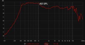
Here is the first frequency response measurement that @WetFartz took with a minidsp umik-1 (mic tip at horn mouth).


XLR mic with audio interface & horn rotating set up is being set up for angular frequency response measurements.. 🙂
XLR mic with audio interface & horn rotating set up is being set up for angular frequency response measurements.. 🙂
Attachments

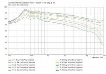
So here is the result of horizontal polar measurements (measurements captured from 0 degrees on axis to 180 degrees off axis).. 🙂
The measurements are gated at 6ms (could have extended it till 9ms in REW I think).
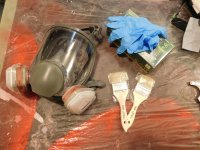
Measurement set up

Impulse response showing relative absence of reflections within gate window

Frequency response curves

Visualization in VituixCAD for normalized polar map

It looks like something happend around 7kHz. Not sure if it is due to driver break up resonances. Don't know what is happening around 1.5kHz as well.
Please share your comments regarding these measurements and whether the horn with this driver is good to fit into a 2-way system (or do we need to make it a 3way with a super tweeter up top)
Thanks
Vineeth
The measurements are gated at 6ms (could have extended it till 9ms in REW I think).
Measurement set up
Impulse response showing relative absence of reflections within gate window
Frequency response curves
Visualization in VituixCAD for normalized polar map
It looks like something happend around 7kHz. Not sure if it is due to driver break up resonances. Don't know what is happening around 1.5kHz as well.
Please share your comments regarding these measurements and whether the horn with this driver is good to fit into a 2-way system (or do we need to make it a 3way with a super tweeter up top)
Thanks
Vineeth
Last edited:
The correct length for my horn is about 98mm (35.6mm round to 50.8mm squared, T=0.7, fc=325Hz).
Attachments
If you used a voltage source amplifier then the hole around 1k5 is related to the driver. Look at the combined impedance. Otherwise you have many sources of possible resonances in your 3d printed horn. An ultimate solution would be to mill it out of a solid block of plywood and the fins made from metal or very hard wood ;-)So here is the result of horizontal polar measurements (measurements captured from 0 degrees on axis to 180 degrees off axis).. 🙂
The measurements are gated at 6ms (could have extended it till 9ms in REW I think).
Measurement set up
View attachment 1188707
Impulse response showing relative absence of reflections within gate window
View attachment 1188699
Frequency response curves
View attachment 1188702
Visualization in VituixCAD for normalized polar map
View attachment 1188703
It looks like something happend around 7kHz. Not sure if it is due to driver break up resonances. Don't know what is happening around 1.5kHz as well.
Please share your comments regarding these measurements and whether the horn with this driver is good to fit into a 2-way system (or do we need to make it a 3way with a super tweeter up top)
Thanks
Vineeth
@docali: Thanks a lot for sharing the adaptor step file. 🙂
Can it be used with any 1.4inch compression driver or is it specific to some driver?
Based on the above Excel sheet, we used a conical adaptor and not an exponential one like the one you gave. We couldn't find the adaptor you gave anywhere on the website. Thanks again for sharing it.
The adaptor that we used could probably be the source of some of the issues, I guess.
The amplifier used for measurements was the following I think:
https://soundfoundations.in/products/sabaj-a30a/
I am guessing it is a voltage source amplifier.
I think @WetFartz has plans to make the horn in wood eventually and this one was meant for prototype use,
My adapter only takes into account the surface area expansion so it is independent of any specific driver. You would have to choose best a driver of the "old school" design with zero or low exit angle. Anyway, there seem to be even new design with the pp ending up directly at driver exit.
I don't expect too much difference with the exponential adapter but I would appreciate if you could make a comparison. But take care to make the adapter almost resonance free. I don't like pure PLA. There is PLA/wood available and even with metal fill. Otherwise take care to damp the adapter very well.
I don't expect too much difference with the exponential adapter but I would appreciate if you could make a comparison. But take care to make the adapter almost resonance free. I don't like pure PLA. There is PLA/wood available and even with metal fill. Otherwise take care to damp the adapter very well.
I wish to have such a large room for measurements! Great!
- Home
- Loudspeakers
- Multi-Way
- 2-way horn system based on the MK3B2