😛
My printer has vouched to not follow this method again. He said it was nothing but a pain to align the various sections. They all went back home with hardened skin on their fingers from the super glue.
2. I'm reconsidering my approach to dampening the horn. My initial plan was to fill the cavities with POP, but I'm concerned that the added weight would cause the PLA surface to sag. I'm now considering the option of attaching felt or thick fabric around the horn. Are there any other ideas or suggestions for dampening the horn effectively?
Edit: I'm intrigued by @DonVK's post on his horn construction and would like to gain a better understanding of the effectiveness of his damping solution.
You might need stiffening and damping depending on the thickness of the walls.
If you can add small barriers (5mm high) to form pockets, you might be able to use casting resin to get strength, damping and bridge the seams.

With todays techniques like 3D printing and CNC milling, I am amazed that with this horn you stick to a rectangular throat, with all the problems of resonances and round to rectangular throat adapters. The original Yuichi A-290 was built with hand tools so the rectangular throat made sense, but today you guys should be able to do better. Joseph Crowe's horns have round throats and nicely rounded inner edges; that should be possible with a Yuichi style horn as well.
Maybe you could design the first (fin) section to have exponential vertical flares as well.
Maybe you could design the first (fin) section to have exponential vertical flares as well.
Just have a look at @pelanj:😛
My printer has vouched to not follow this method again. He said it was nothing but a pain to align the various sections. They all went back home with hardened skin on their fingers from the super glue.
https://www.diyaudio.com/community/...-neile-alo-horn-by-sphericalhorns-net.390581/
He managed to put the parts well together although there a re still resonances.
How about wearing gloves when working in accordance with health and safety regulations in such a case? 😎 But apart from that, I think the result achieved is very impressive. Congrats!
I don't see any resonances inherent to the rectangular throat or any problem making a round to square adapterWith todays techniques like 3D printing and CNC milling, I am amazed that with this horn you stick to a rectangular throat, with all the problems of resonances and round to rectangular throat adapters.
The good thing about a design like this is that it offers the possibility for improved performance in effectively the same size and style and can still be made by hand tools for those that want to. Whether a horn can be "better" is a matter of defining how that better will be measured. This horn offers a very particular directivity pattern that someone may like or not.The original Yuichi A-290 was built with hand tools so the rectangular throat made sense, but today you guys should be able to do better.
Rounding the inner contours has a surprisingly limited effect in almost all horn and waveguide designs. Just because something looks like it should perform better does not mean that it will. Simulating or measuring a prototype shows this to be true.Joseph Crowe's horns have round throats and nicely rounded inner edges; that should be possible with a Yuichi style horn as well.
@docali has other designs that have no sharp edges internally and go straight from round without an adapter.
https://sphericalhorns.net/2022/09/06/acoustic-loading-optimized-william-neile-horns-1in0-prototype/
I see these as both being high performance horns that are different from each other.
Area expansion is what matters more so than shape, it would be much more difficult to calculate and build with very little change in performance.Maybe you could design the first (fin) section to have exponential vertical flares as well.
For measuring the On and Off axis frequency responses for this horn, does the VituixCad suggested standard procedure of measuring speakers work?
I mean aligning the mouth of the horn with the middle of the turntable (for centre of rotation) and measuring it from 1m away (since the horn width is about 65ish cm)?
I mean aligning the mouth of the horn with the middle of the turntable (for centre of rotation) and measuring it from 1m away (since the horn width is about 65ish cm)?
@vineethkumar01 has been kind enough to provide the dimensions for the adaptor. This is the inner piece which will then be clad in plywood, including the flanges at both ends.

These are the wooden sections that'll cover the throat of the adaptor. CNC work.

These are the wooden sections that'll cover the throat of the adaptor. CNC work.
According to my printer, the side walls of the horn are protruding by approximately 1.5mm at the rear. To accommodate this protrusion, the throat has been designed accordingly. Additionally, the newly created notch will serve as a helpful guide to ensure perfect alignment between the horn and the throat. Sanding and filling to follow.

To have the display from Vituix be valid the standard procedures need to be adhered to otherwise there will be errors in the calculations.For measuring the On and Off axis frequency responses for this horn, does the VituixCad suggested standard procedure of measuring speakers work?
I mean aligning the mouth of the horn with the middle of the turntable (for centre of rotation) and measuring it from 1m away (since the horn width is about 65ish cm)?
Care would need to be taken to make sure that there are no close surfaces from the measurement setup that will interfere.
1m will still be within the nearfield for a 65cm wide horn, so the response further out will be different. Larger speakers need longer measurement distances so it can be hard to measure them accurately in a home environment. Measurements near the mouth can still be useful as long as it is understood that all the diffraction effects will not be present.
Actually @fluid helped me with the adaptor.
So Thanks to him.. 🙂
@fluid: If the diffraction effects are not captured well, then wouldn't it affect the crossover design?
Could you please tell us more about how we can ensure that we get reliable measurements for the crossover design for this horn.
Would a 1.5 or 2m measurement be enough? Can we do something with ground plane kind of measurements? Since the typical crossover with the 15inch woofer may fall somewhere in between 600-800Hz (a region where the gated measurement limitations might affect more), what can we do about this?
3 times the longest width is usually a safe way to get a farfield distance. So a 2m measuring distance is enough, the difference between 1m and 2m may not be very significant. You can try both and compare to see the tradeoff in the measurements of reducing reflection free time vs not fully being in the farfield. With a short gate time the lack of frequency resolution will wipe out a lot of detail anyway. That is where a nearfield measurement can be used to try and make sure that no problematic resonance is hiding.
Ground planes can work but then there is the slight complication of the baffle size being doubled, so the diffraction response is not quite right without compensation and the need to tilt the speaker which makes polar measurements more difficult.
Currently there is no handy and cheap solution other than extending the gate time.
If you have an empty nuclear power station you can do this 🙂
Wow.. That is quite some measurement set up.. 😱
Looks like the diy version of Dynaudio Jupiter set up.. 😀
Looks like the diy version of Dynaudio Jupiter set up.. 😀
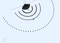
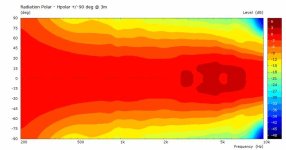
I was thinking about how the polar would change if you had to measure closer than ideal. This assumes 4Pi space, so it's high enough off the floor and from other objects to support the measurement gate time. Akabak sim was used with far field turned off, and the pic shows the measurement points and rotation axis.
[edit] - swapped graphs for smoothed ones.
[edit] - swapped graphs for smoothed ones.
Attachments

Last edited:
@DonVK
Thanks a lot for sharing these simulations.
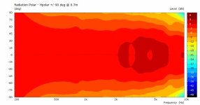
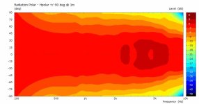
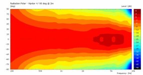
The true polar pattern width seems more evident at a 3m distance, especially at higher frequencies. There seem to be some peaks & dips in the frequency response from 3k to 7k whose nature slightly varies according to the distance used for measurement.
However, the 2m measurements seems close.
If possible/available, could you also share the unnormalized frequency response curves for the different angles.
A view like this:

This is just so that @WetFartz has some sort of reference about what the frequency response looks like during the actual measurement session
Thanks
Vineeth
Thanks a lot for sharing these simulations.
The true polar pattern width seems more evident at a 3m distance, especially at higher frequencies. There seem to be some peaks & dips in the frequency response from 3k to 7k whose nature slightly varies according to the distance used for measurement.
However, the 2m measurements seems close.
If possible/available, could you also share the unnormalized frequency response curves for the different angles.
A view like this:
This is just so that @WetFartz has some sort of reference about what the frequency response looks like during the actual measurement session
Thanks
Vineeth
That also looks normalized, to get non normalized polar curves is a little tricky as the model was solved with constant velocity not constant acceleration, I think that needs a resolve for that change rather than a different observation script like Don used above.If possible/available, could you also share the unnormalized frequency response curves for the different angles.
A view like this:
Thanks @fluid for the explanation. 🙂
You are right. My plot above is also normalized. I didn't have access to an unnormalized plot.
I was trying to say that if possible can we also look at the discrete frequency response curves corresponding to different angles (unnormalized if that is doable) instead of the polar plot. If it involves more simulation time and effort, I think we need not look at it since the general trends are already visible in Don's plots.
Anyway, we would need actual measurements of the horn to move forward.
For now, I will try to help @WetFartz to take some measurements of the horn once he has the equipment & horn ready.
(I wish I could help him with measurement set up etc, in person but since I live about 400km away from him, it is not practical. 🙂 )
- Home
- Loudspeakers
- Multi-Way
- 2-way horn system based on the MK3B2