That's my Excel file. Glad you found it useful.The adaptor we used is based on the excel sheet calculator here:
https://www.diyaudio.com/community/...s-to-compression-drivers-a-discussion.397699/
Here is a snapshot of the relevant calculations related to the internal geometry of the HF146 driver
But... that's an extreme driver-horn mismatch!
The driver's internal throat is short and with a large exit angle, resulting in a VERY high flare rate (>900 Hz equivalent exponential), whereas the horn has a much lower initial flare rate.

The wide conical throat of the driver is not damping the second driver resonance at 1.5K very well and below that the impedance match isn't as good as it could be. A ring insert adapter going down to the phase plug would help to avoid that problem and the HF146 is a good candidate for that idea. Overall it looks pretty good and as the simulations predicted. Above 15K is difficult for many 1.4" compression drivers and 3D printed fins in PLA with no reinforcement or damping could well be contributing to the messy HF.Don't know what is happening around 1.5kHz as well.
Please share your comments regarding these measurements
Thanks @fluid 🙂
Now I have a question
1) How do we design a ring insert for this driver/horn combination?
Is the ring insert just a cylinder of diameter 25.4 mm (internal diameter of throat near phase plug exit) which sort of reduces the exit angle of the throat from 29 degrees conical to zero degrees. And then we design a new adaptor for this new transition from 25mm diameter throat exit to the 50.8mm square inlet of the horn. Or do we have to design a complete new throat adaptor for a 25.4mm to 50.8mm transition with 2 cm length of the adaptor (depth of the throat) inside the driver throat?
Please let me know more about this and how we can design a ring insert.
Thanks
Vineeth
You want the internal surface to make a smooth expansion between the end of the phase plug and the square opening of the horn in a similar way to the one docali showed above. The outer surface would be made to match the conical throat of the driver, probably with a plate over the driver mounting surface so it can be held on firmly.
So not a cylinder, either a conical shape or exponential or Hypex to match the Fc and T of the main horn. The exit angle would then be considered to be zero.
So not a cylinder, either a conical shape or exponential or Hypex to match the Fc and T of the main horn. The exit angle would then be considered to be zero.
Measuring was a fun experience!
Many thanks to @vineethkumar01 for spending his weekend helping me sort out and configure the software. We initially had no output. We thought it was a driver/software issue. After much fiddling we swapped the input cable from L to R on the amp, and voila! it worked. Quirks of the amp.
This was a test piece, and the final horn would be milled out of solid wood. I'm also checking the feasibility of the adaptor milled from solid wood for testing purposes. I plan to drill holes in the fins and fill them with resin to make them solid. I also hadn't applied POP on the side wall. When I have the new adaptor we can measure again and see if we have improvement.
Ok.
Thanks again @fluid.
Just to confirm that I have got the idea correctly, now we want to make a throat adaptor for a 25.4mm inner diameter round to 50.8mm square adaptor of sufficient length to get the flare rates matching with the assumption that it is zero degrees exit angle. The new adaptor starts right from the phase plug exit.
But then wouldn't the adaptor need to be very very thin in the area very near to the phase plug exit so that we dont use up the space near the 25.4mm dia phase plug exit?
This is how the conical exit of the driver looks like

We want to ensure that the outer surface of the new adaptor especially the part that goes inside the throat fits properly on the orange colored existing conical adaptor in above pic. So the outside of the insert that we design needs to be conical but inside will be designed as per a smooth curve.
One more doubt I have is the following. Now I know how to make conical adaptors using fusion's morph feature. But how do we make an exponential curve like the one @docali designed. Exponential curve with Fc = 325 and T = 0.7. Is there any equation available somewhere which describes this curve. If I can make the curve in excel sheet of somewhere else probably I can rotate it in fusion to form the inner surface and then thicken it appropriately to get the outer surface also..
Please let me know if my understanding above is correct.
Thanks again @fluid.
Just to confirm that I have got the idea correctly, now we want to make a throat adaptor for a 25.4mm inner diameter round to 50.8mm square adaptor of sufficient length to get the flare rates matching with the assumption that it is zero degrees exit angle. The new adaptor starts right from the phase plug exit.
But then wouldn't the adaptor need to be very very thin in the area very near to the phase plug exit so that we dont use up the space near the 25.4mm dia phase plug exit?
This is how the conical exit of the driver looks like
We want to ensure that the outer surface of the new adaptor especially the part that goes inside the throat fits properly on the orange colored existing conical adaptor in above pic. So the outside of the insert that we design needs to be conical but inside will be designed as per a smooth curve.
One more doubt I have is the following. Now I know how to make conical adaptors using fusion's morph feature. But how do we make an exponential curve like the one @docali designed. Exponential curve with Fc = 325 and T = 0.7. Is there any equation available somewhere which describes this curve. If I can make the curve in excel sheet of somewhere else probably I can rotate it in fusion to form the inner surface and then thicken it appropriately to get the outer surface also..
Please let me know if my understanding above is correct.
I think the falling apart above 7 kHz is just a real life vs model for the fins - the input simply won't be coherent enough for that to work properly. The ring is the only hope here. I would be surprised if it helped but it's definitely worth a try.
(Maybe the front orange conical duct could be replaced as a whole but that would need to be found out by further inspection of the construction.)
(Maybe the front orange conical duct could be replaced as a whole but that would need to be found out by further inspection of the construction.)
Or maybe standing waves at the rectangular throat? Two inches is around 7k....I think the falling apart above 7 kHz is just a real life vs model for the fins
It doesn't look like standing waves, it's a lot more chaotic. It's simply an interference of several sources with different strenghts and phases. As I see the problem, the fins divide the input wavefront at different parts that are not equal in amplitude nor phase. These separated channels, at the end of the fins, are then let to sum (interfere) over a much larger area/volume, which just doesn't sum nicely. It can thus well be that the fins actually make more harm than good. Well, at least that's the concern I already expressed in the past and it seems to confirm. It just doesn't always go as smoothly as our simplified models predict...
Last edited:
There is a round to square throat adapter, so the input wavefront is distorted to begin with; that is simple physics.
The fins are there to strive for CD, possibly at the expense of linear frequency response; when I am right these two don't go together.
Joseph Crowe horns have round throats, no fins, more linear frequency response, less CD. At least that's what I understand.
What is better?? Compare and pick your poison 😉
That doesn't have to be a problem per se, but it doesn't help either, I would agree with that.There is a round to square throat adapter, so the input wavefront is distorted to begin with; that is simple physics.
Circular shape doesn't have to be necessarily better in this regard, however. The problem is the division.
No, that's not true, those two attributes are certainly not mutually exclusive.... strive for CD, possibly at the expense of linear frequency response; when I am right these two don't go together.
Last edited:
Maybe not mutually exclusive, but CD horns need EQ.
NicoB wrote:
Energy is not free: A horn radiates energy according to his form, so a on-axis flat horn like the one of Joseph or a JMLC for example cannot be CD (Constant Directivity).
When we add a CD behavior we will create a bell form response, that is inevitable, physics laws.
What is pushed to the off axis is taken from on axis basically.
So a CD horn needs EQ, people that are allergic to DSP will not like this kind of horn. it’s just a matter of choice if you want CD behavior or a flat on axis response, but both not.
So Joseph Horn is not CD, it’s just a matter of choice.
In more, fins horns will always have a particular dispersion, they concentrate the +/-30 in constant SPL when on a regular horn it’s +/-15°, it’s due to fins behavior and cannot be reproduced otherwise and it’s what gives the natural in-room listening experience.
For linear response, if we talk about whether the global form of the raw response is linear or not, it’s not the point, a flat raw response just indicate that the horn is not CD, no more.
It’s the mid-range narrowing and beaming (accidents) that are important and it’s mainly relative to the mouth, rounded help but rounded with precise simulation (FEA helps a lot on it).
It’s very hard to remove the midrange narrowing completely without doing a very large horn. Midrange beaming yes. But it’s not just about rounded flare, it’s also a matter of acceleration/deceleration (Mabat will be agree with this 😀)
Then there is the finger response due to distance between fins exit, that is another “problem” that can be completely solved too.
For the dispersion angle, 90° it’s good for our in-room listening distance (2.5 to 5/6m), further we will have to reduce the coverage (80/70/60°), closer to open it to 100/110° as the monitoring speaker does, with a tweeter in a WG like Somasonus it’s good.
In a way yes, it's what I have done, very difficult to produce indeed. In some month I will publish a polar response of mine Bi-radial.
I will put the Docali one in FEA for see what's happen right now 😀.
NicoB wrote:
Energy is not free: A horn radiates energy according to his form, so a on-axis flat horn like the one of Joseph or a JMLC for example cannot be CD (Constant Directivity).
When we add a CD behavior we will create a bell form response, that is inevitable, physics laws.
What is pushed to the off axis is taken from on axis basically.
So a CD horn needs EQ, people that are allergic to DSP will not like this kind of horn. it’s just a matter of choice if you want CD behavior or a flat on axis response, but both not.
So Joseph Horn is not CD, it’s just a matter of choice.
In more, fins horns will always have a particular dispersion, they concentrate the +/-30 in constant SPL when on a regular horn it’s +/-15°, it’s due to fins behavior and cannot be reproduced otherwise and it’s what gives the natural in-room listening experience.
For linear response, if we talk about whether the global form of the raw response is linear or not, it’s not the point, a flat raw response just indicate that the horn is not CD, no more.
It’s the mid-range narrowing and beaming (accidents) that are important and it’s mainly relative to the mouth, rounded help but rounded with precise simulation (FEA helps a lot on it).
It’s very hard to remove the midrange narrowing completely without doing a very large horn. Midrange beaming yes. But it’s not just about rounded flare, it’s also a matter of acceleration/deceleration (Mabat will be agree with this 😀)
Then there is the finger response due to distance between fins exit, that is another “problem” that can be completely solved too.
For the dispersion angle, 90° it’s good for our in-room listening distance (2.5 to 5/6m), further we will have to reduce the coverage (80/70/60°), closer to open it to 100/110° as the monitoring speaker does, with a tweeter in a WG like Somasonus it’s good.
From a technical design standpoint I think a revised A290 would need very complex 3D CAD modelling through the throat section, something much more organic than the parallel walls and basic geometric shapes of the existing design.
In a way yes, it's what I have done, very difficult to produce indeed. In some month I will publish a polar response of mine Bi-radial.
I will put the Docali one in FEA for see what's happen right now 😀.
Last edited:
@vineethkumar01 , @WetFartz
IMO you need to slow down and start to eliminate some variables that might be causing these issues.. A few experiments will tell you if the problem is from either measurement or construction. What material is in the space between the horn skin and the thin plywood (?) outer skin? Are we sure that every interface is sealed properly , either perfectly flat or with a gasket. If it were my horn I would try the following:
1) single baseline measurement on axis
2) put the horn on a folded blanket to decouple (and damped) it from the stand, take another measurement
3) wrap a thick blanket around the horn body and take another measurement
If all 3 look the same you have a good construction, and can start to look at the next things.
[edit] if you want I can rerun the simulation with your particular adapter, I think its is a simple lofted conic, is that right?
Last edited:
@DonVK
Thank you for these suggestions. We will try out the steps you mentioned next time we measure.
@WetFartz can elaborate on more details about the horn construction related aspects as I have only seen it in pictures.. 🙂
For now, this is our 6ms gated on axis measurement of the horn with mic 2m away from the horn mouth


There are indications of some dips and peaks in the impedance magnitude response above 8kHz above which also coincides with some of the dips and peaks in frequency response. These are even in the raw driver impedance measurements as shown below.

Even Faital pro's data sheet measurements show these but I think their magnitude response is much smoothed

If I just apply 1/12 octave smoothing to the above captured measurement, it looks like below.

Looks much cleaner and similar to data sheet.
From above, I am guessing that the driver break up modes could be causing some of the issues that we have been seeing. The resulting out of phase radiation from different parts of the diaphragm may be causing the kind of comb filtering sort of effects that we are seeing at high frequencies I think.
For now, @WetFartz is working on the horn trying to damp the sidewalls and the fins more. I will try to design a new adaptor based on fluid's suggestions for the ring insert.
Regarding the current adaptor, it is as you said. It is a simple lofted conic of 11.6cm length. If it would be possible for you to run some sims with the adaptor, we might get some more clues I guess. Thanks a lot for trying to help out.
[Edit]
Adding energy decay & distortion plots for the above measurement


Thank you for these suggestions. We will try out the steps you mentioned next time we measure.
@WetFartz can elaborate on more details about the horn construction related aspects as I have only seen it in pictures.. 🙂
For now, this is our 6ms gated on axis measurement of the horn with mic 2m away from the horn mouth
There are indications of some dips and peaks in the impedance magnitude response above 8kHz above which also coincides with some of the dips and peaks in frequency response. These are even in the raw driver impedance measurements as shown below.
Even Faital pro's data sheet measurements show these but I think their magnitude response is much smoothed
If I just apply 1/12 octave smoothing to the above captured measurement, it looks like below.
Looks much cleaner and similar to data sheet.
From above, I am guessing that the driver break up modes could be causing some of the issues that we have been seeing. The resulting out of phase radiation from different parts of the diaphragm may be causing the kind of comb filtering sort of effects that we are seeing at high frequencies I think.
For now, @WetFartz is working on the horn trying to damp the sidewalls and the fins more. I will try to design a new adaptor based on fluid's suggestions for the ring insert.
Regarding the current adaptor, it is as you said. It is a simple lofted conic of 11.6cm length. If it would be possible for you to run some sims with the adaptor, we might get some more clues I guess. Thanks a lot for trying to help out.
[Edit]
Adding energy decay & distortion plots for the above measurement
Last edited:
@DonVK There's POP in that space. Specifically the top and the bottom of the printed horn. I had left out the sidewalls as they looked and sounded "inert" enough. But I now plan to fill this space with POP, and also fill the fins with resin to make them solid. And with the new adaptor incoming we hope to measure this soon again.
Edit: The current adaptor is pretty solid. The printed part and the plywood are sandwiched between a layer of a mixture of sawdust and glue. There are no airgaps.
Edit: The current adaptor is pretty solid. The printed part and the plywood are sandwiched between a layer of a mixture of sawdust and glue. There are no airgaps.
Last edited:
I've always wondered how it can be that the impedance look so weird, I mean the region 400 Hz - 1 kHz. I've never seen that on any device I've been ever working with. Are those all high-Q resonances induced by the horn, or what?
(You would need a pretty long time window to capture that acoustically, BTW, if it's actually in the radiated sound.)
(You would need a pretty long time window to capture that acoustically, BTW, if it's actually in the radiated sound.)
Last edited:
I didn't know how to make an exponential adaptor.
So I tried out the conical adaptor excel sheet I used before from @marco_gea
Based on the input parameters, it gives me a length of 19.6cm for the adaptor.
Can someone please check if I have input the parameters correctly? (with the ring insert, I am assuming that the throat length can be set to zero)
Last edited:
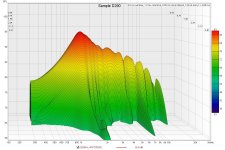
@WetFartz
The previous tests were for unintentional radiation from the horn walls or the stand (stacked chairs).
The next test I would do is check for internal resonances using a CSD waterfall using REW. You can use the on axis baseline for this. I've attached a sample so you can see what I mean. The resonances are at [2Khz, 8Khz, 18Khz].
Attachments
- Home
- Loudspeakers
- Multi-Way
- 2-way horn system based on the MK3B2