Gnobody, thank you again for taking the time to explain this. And thanks for the warning regarding the possible dangers when using headphones.
You said this would not be the best but the simplest way to attenuate. I assume the "better" way would be to attenuate with a pot / voltage divider /series resistor "in front" of the headphones but that would require a switch to select between speaker out and headphones out and it appears the whole idea of this circuit is simplicity and low parts count.
i will certainly use a pot in series - or a pot in series with a resistor. i'd rather start out with not enough volume than with too much.
You're very welcome. There are few things more sad than a deaf musician...and there are a lot of them! 🙁Gnobody, thank you again for taking the time to explain this. And thanks for the warning regarding the possible dangers when using headphones.
I had a loud car in my twenties (previous owner ripped holes in the mufflers, and I was a starving student who didn't have the money to replace them), and I've been in a few situations where I was on stage with a drummer and a 15-watt tube guitar amp, and no ear-plugs; most people don't think a 15 watt guitar amp is particularly loud, but it is, really, and apparently that has been enough to damage my hearing. Now I have some tinnitus in my left year - hissing and whistling that never goes away.
Be wiser than I was, protect your ears! 🙂
Exactly!I assume the "better" way would be to attenuate with a pot / voltage divider /series resistor "in front" of the headphones but that would require a switch to select between speaker out and headphones out and it appears the whole idea of this circuit is simplicity and low parts count.
With loudspeakers, we go to some trouble to ensure the amplifier has a low output impedance, which produces tight, well-controlled bass from the loudspeaker. If the amplifier has too much output impedance, the bass is likely to become boomy, flubby, poorly damped. Bass is damped (controlled) when the back-emf from the moving loudspeaker coil causes a damping current to flow through the amp and speaker, but if there is too much resistance in series, the current decreases, and the bass becomes poorly damped.
Headphones are basically tiny loudspeakers, so exactly the same physics will apply, though I have never read anything in print about it.
When we insert a big resistor in series with the headphones, that must have an effect on the bass damping. How audible that is, I don't know. Since you'll be listening to a guitar (and not drums, bass, etc), this probably won't be an issue.
As you said, by using a potential divider between amp and headphones, we can do better. By choosing the resistor values appropriately, we can still present the headphones with a reasonably low source impedance, while at the same time cutting down the signal strength to them.
Perfect! 🙂i will certainly use a pot in series - or a pot in series with a resistor. i'd rather start out with not enough volume than with too much.
-Gnobuddy
Back in the day, (seventies), before minimalism, almost all amplifiers had a headphone jack and almost all of them had a 32ohm (or thereabouts) resistor in series with the signal.When we insert a big resistor in series with the headphones, that must have an effect on the bass damping. How audible that is, I don't know.
Headphones were thus designed around that situation.
Move onto the tape & mp3 boom later in the century and after and output resistances (and available voltage swings) drop due to the constraints of battery power.
As a result we saw a range of headphones designed for that situation (e.g. Grado SR-60s being the most noteworthy).
We also had lots of headphones (often "branded") from with deliberately lumpy bass as this was a major selling point. One had to hunt to find designed-flat headphones at a decent price point.
So we ended up with two (non) standards. And as a result headphone amps/DACs started popping up with two outputs: 0 ohm and 32ohm.
What's happened in the last decade? I have no idea.
Last edited:
Thanks for filling us in on the headphone-damping past!
I'm semi-kidding, but not entirely. Amazingly, I constantly encounter people listening to music using their tablet or phone's built in speaker. It sounds like a broken Hi-Fi speaker with only the dome tweeter still working, and a hankerchief thrown over that to block the top two octaves.
-Gnobuddy
People started listening to music using the tiny built-in speaker in their smartphone, frequency response from 1 kHz to 5 kHz or thereabouts. 😱What's happened in the last decade? I have no idea.
I'm semi-kidding, but not entirely. Amazingly, I constantly encounter people listening to music using their tablet or phone's built in speaker. It sounds like a broken Hi-Fi speaker with only the dome tweeter still working, and a hankerchief thrown over that to block the top two octaves.
-Gnobuddy
Headphones are telephone earpieces on a strap. 100dB SPL from a couple of volts is VERY VERY old news.
I do not remember any 32 Ohm phones before WalkMan. Several ~~8r, mostly 60-150r descended from the best of the Studio Line monitors. Single resistor on a loudspeaker output was very liable to to blow phones of some impedance.
I would not call 125dB SPL "instantly deaf" but I agree it is not good for you.
The main thing is to Be An Adult. Don't drink after you fall on the floor. Don't toot after you float to the ceiling. And don't turn-up sound endlessly.
thanks for all the explanations!
parts arrived from mouser today and i'll start breadboarding tomorrow. i'll let you know how it goes....
parts arrived from mouser today and i'll start breadboarding tomorrow. i'll let you know how it goes....
I have zero medical qualifications, and will take correction from anyone who is better qualified when it comes to human hearing.I would not call 125dB SPL "instantly deaf" but I agree it is not good for you.
That said, I did do some layperson-level research. There is TSH ("Temporary Shift of Hearing"), loudness-induced hearing damage that fades with time, so that your ears are restored to normal eventually. Then there is PSH ("Permanent Shift of Hearing"), when the SPL is loud enough to cause hearing damage that is permanent, i.e. the ears do not recover.
A while ago, I looked up tables of SPL v.s. exposure time necessary to cause permanent hearing damage. At 125 dB, the time to PSH was too short to list, i.e. virtually instantaneous. At least one write-up suggested that a single musical note at this SPL was sufficient to cause permanant damage; most musical notes are shorter than one second. So, not "instantly deaf", but "virtually instantaneous hearing damage".
There have been rock bands that produced 125 dB at the ears of the audience. Without hearing protection, audience members would have left those shows with permanent hearing damage.
Agreed, in normal music listening, this is a perfectly reasonable strategy.And don't turn-up sound endlessly.
However, if you look at the Ruby amp schematic, it is a perfectly ordinary LM386 power amp preceded by a JFET common-source buffer. There is no design mechanism to cause early onset of distortion for guitar; distortion only starts when the LM386 is driven to its maximum output signal voltage, so that its output begins to clip.
In other words, the Ruby amp is Hi-Fi clean until driven to full power, at which point, it is ear-shatteringly loud in headphones. It's like a Fender Twin in that regard, except the Ruby is actually louder at the onset of clipping...80 watts into a 100 dB@1W guitar speaker produces "only" 119 dB, while the Ruby will spit out 125 dB from headphones!
There is a secondary feature of the (Ruby + headphones) that makes SPL-induced hearing damage even more likely. The LM386, like all circuits with large amounts of negative feedback, clips abruptly, creating lots of high-frequency sound in the process. A normal guitar speaker would roll off frequencies above maybe 3 - 4 kHz, but headphones will not. It is known that high frequencies at high SPL are particularly damaging to hearing.
As mentioned, I have no medical credentials whatsoever. That said, my laypersons opinion of the (Ruby + headphones) is that is a terrible idea, a bad design, specifically because it is so designed that it will destroy your hearing if you turn it up until it distorts, which most guitarists will do.
This could have been done much better - wire the JFET as a common-source amplifier, wire a pair of clipping diodes in reverse-parallel from its output to ground, stick a volume pot there, and now you have the ability to dial in distortion (via guitar volume knob) and loudness (via post-JFET volume pot) independently.
-Gnobuddy
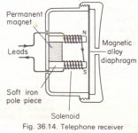
The telephone earpieces I opened as a child were a moving-iron design, with a big stationary electromagnet, a small polarizing permanent magnet, and a thin sheet of some magnetic material as the diaphragm (like the first attached image.)Headphones are telephone earpieces on a strap. 100dB SPL from a couple of volts is VERY VERY old news.
I remember that the coils contained lots of turns of hair-thin copper wire, but I don't remember their DC resistance; faint memory says maybe as much as 1 kilo-ohm.
Well before the Walkman was invented, my father had a Sony AM/shortwave portable radio that came with a single earbud (for those too young to remember, AM and shortwave radio are both mono.) I opened it up to study it when he wasn't looking, of course.
It was a miniature version of the telephone earpiece, with a tiny permanent magnet in the shape of a ring, with a thin sheet of magnetic material laid on one end, and a small 8-ohm coil of copper wire stuffed inside, wound on a central metal pole-piece, itself attached to a thicker disc of magnetic material that closed off the bottom of the magnetic ring, completing the magnetic circuit. A moving-iron design, with lousy sound quality and lousy sensitivity, but it was being driven by a transistor amplifier running on 9 volts, so it was more than loud enough.
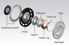
The headphones Sony supplied with their Walkman more than a decade later came from a different evolutionary origin altogether. The story I read is that, on a whim, a Sony engineer fed music into one of the company's existing moving-coil microphones, held it up to his ear, and was pleasantly surprised at the excellent sound quality. He then slapped together two of these to make a pair of moving-coil headphones, and when his bosses heard them, they realized they had something that no other audio company had: a pair of comfortable, light-weight headphones that produced extremely good sound quality. These were essentially a pair of tiny moving-coil loudspeakers (second attached image), very much like some dome tweeters.
The Walkman was then designed around these headphones, and went on to be an enormous success for Sony. Portable cassette players existed already, but tended to be low-quality mono devices. The Walkman was stereo from the start, and the new Sony headphones sounded so much better that it was astonishing.
Decades later, things came full circle; after the home recording studio became a possibillity, there are many stories of home recordings made by cash-strapped musicians using an old pair of Walkman headphones as microphones. 🙂
-Gnobudy
Attachments
so i put together the first prototype on a breadboard and attached it to an 8ohm speaker. there‘s tons of noise pickup but i assume that is normal for a breadboard circuit without an enclosure to shield it. apart from that the amp sound surprisingly good. strange malfunction: as soon as i turn down the volume with the pot on the guitar even a tiny bit the sound is cut off completely. guess i‘ll have to troubleshoot tomorrow.
Are you perhaps using a high-resistance volume pot, such as 1 Meg, 500k, etc? If so, that can cause this symptom....as soon as i turn down the volume with the pot on the guitar even a tiny bit the sound is cut off completely.
The trouble is that the LM386 has a relatively low input impedance of only 50k. It works best with a volume pot that has 100k or less resistance. A 47k, 22k, or 10k log pot (in the USA: 50k, 25k, or 10k) will work well.
The low input impedance of the LM386 is the reason why the Runoff Groove fellows added the JFET input stage. It prevents the LM386 from loading down the guitar and causing a loss of treble (the dreaded "tone suck" in American parlance.)
-Gnobuddy
Yes, it's interesting. I got "seriously into" headphones in the early nineties: you know, Sennie HD-560/580, Grados etc, then the inevitable move to Stax ear phones. All of which needed a decent amount of oomph to drive.I do not remember any 32 Ohm phones before WalkMan. Several ~~8r, mostly 60-150r descended from the best of the Studio Line monitors. Single resistor on a loudspeaker output was very liable to to blow phones of some impedance.
I just repaired a set of SR-80s - 32ohm DC resistance. Somewhere I have a faulty set of SR-60s. If I can find I'll measure them, as you could attach them to anything and they still sounded good, where as the "better" stuff sounded thin and awful on portables.
Whereas the few older headphones weren't so problematic.
(I still have my Panasonic SL-SX220 with it's then-revolutionary 1 second "antishock" buffer but that's a story for another thread).
a good night's sleep cures most circuit problems. i twisted the in- and output wires, moved the power supply cap (200uF) closer to the opamp and most of the noise is gone. after removing the input buffer the noise is further reduced and I can now also use the volume pot on my guitar. so i bet something must be wrong with that buffer - i bet i wired it the wrong way or something. i really don't have a lot of experience working with transistors and their pinout always confuses me ...
apart from that - i used the (bufferless) ruby in bassman mod configuration all morning. my wife hasn't left me (yet) and i must say it sounds quite amazing.
apart from that - i used the (bufferless) ruby in bassman mod configuration all morning. my wife hasn't left me (yet) and i must say it sounds quite amazing.
Congratulations! 🙂
The other thing that can be overlooked is top view v.s. bottom view. Datasheets tend to show the bottom view - if you're used to looking at the circuit board from the component side, you're seeing the top view, so adjust accordingly.
Your DMM can help with diagnosis. When the JFET buffer is working, the gate will be at zero volts DC, the drain at +9V, and the source somewhere between +1 and +5 volts.
-Gnobuddy
For the J112, the middle pin is the source. Connect that to ground, and you have a 50:50 chance of getting the other two right. 🙂...transistors...pinout...
The other thing that can be overlooked is top view v.s. bottom view. Datasheets tend to show the bottom view - if you're used to looking at the circuit board from the component side, you're seeing the top view, so adjust accordingly.
Your DMM can help with diagnosis. When the JFET buffer is working, the gate will be at zero volts DC, the drain at +9V, and the source somewhere between +1 and +5 volts.
-Gnobuddy
so i put that input buffer back into the circuit and the trouble starts all over. the amp worked fine without the buffer but as soon as i put that JFET in I get all kinds of weird farting noises, buzz, hiss, you name it. the transistor is certainly installed right now - i triple checked. also that "pot interaction" is back. as soon as i move the guitar put just a tiny bit the sound just cuts off. If i keep turning the pot the sound reappears in a very muffled and distorted kind of way and disappears again. what to do?
May be high frequency oscillation, due to poor circuit design and/or layout....worked fine without the buffer but as soon as i put that JFET in I get all kinds of weird farting noises, buzz, hiss, you name it.
Check out the fixes in the attached image, which might help. Add 0.1uF - 1uF ceramic or film cap as close as possible to LM386 power pins. Add 1k or similar decoupling resistor between +9V and JFET drain. Add 10uF decoupling cap for JFET.
Make sure output wires to speaker/headphones are kept far from JFET gate and copper traces connected to it.
Leaving off that ceramic cap across the LM386 power pins was a major mistake on the part of the Runoff Groove people. Most chip amps are unusable without this.
-Gnobuddy
Attachments
thanks, i'll try that later today. I also googled the topic and people seem to agree that you have to "bypass the LM386 like crazy" 🙂
another general question: why do we use the negative (-) input to feed the audio signal? Most circuits in the datasheet seem to use the positive (+) input.
Thanks.
another general question: why do we use the negative (-) input to feed the audio signal? Most circuits in the datasheet seem to use the positive (+) input.
Thanks.
Some of the circuits from Runoff Groove show evidence that the designer(s) don't know much electronics. So circuits found there don't always have a good reason for being the way they are....why do we use the negative (-) input to feed the audio signal? Most circuits in the datasheet seem to use the positive (+) input.
That said, the LM386 was designed as a low-cost, low-power amp that uses a bare minimum of external components to keep things simple and cheap for manufacturers of inexpensive audio products. Unlike most chip amps, the LM386 has an oddball internal circuit design that lets you use either the inverting (-) input, or the non-inverting (+) input, or both at the same time, without much difference in input impedance.
When you're not dealing with an LM386, but rather with an op-amp or more conventional class AB chip amp, there are usually substantially different consequences for amplifier designs using the (+) and (-) inputs, known as non-inverting and inverting amplifiers respectively. Perhaps the one that's most significant is that the input impedance of an inverting amplifier tends to be uncomfortably low for many audio applications.
-Gnobuddy
Gnobody, thanks again for sharing all your knowledge.
I tweaked the layout a bit last night and now it works just fine. I'm not sure what did the trick. I replaced the input with a shielded cable (instead of twisted pair). Also I moved the 220uF cap that sat between (+) and (gnd) somewhere on the "powerrail" of the breadboard to sit right above the opamp between pins 3+4 (gnd) and 6 (+). In addition i put a 0.1uF ceramic cap in parallel with the 220uF cap.
regarding the input: so in your opinion it would not matter whether one used the inverting or non inverting input on the LM386, right?
regarding the ROG designers not knowing much about electronics: I've tweaked and built a few hifi circuits over the last couple years (with a lot of help from this forum) and I always had the impression that people are very passionate about getting the most out of the circuit (low THD; perfect RIAA, low noise, etc...). With guitar electronics I get the impression people have more of a "let's see if this works" attitude.
You're very welcome. Glad to help!Gnobody, thanks again for sharing all your knowledge.
Congratulations!...now it works just fine.

All good moves....shielded cable...moved the...cap...right above the opamp...0.1uF ceramic cap in parallel with the 220uF cap.

Though this is an audio amp, the unwanted oscillation often occurs at radio frequencies, where a couple of inches of copper trace has significant inductance. So a filter cap that's a few inches away becomes ineffective.
That's also the reason for the small-value ceramic cap in parallel - electrolytic caps have significant self-inductance due to the coiled plates inside and long leads, and at radio frequencies, that stray inductance stops them from working well as filter caps. The little ceramic cap takes over at those high frequencies.
Not really. Both behave about the same electrically for the LM386, the only difference being an overall phase reversal at the speaker in the inverting case. This makes no difference at all unless you use a stereo guitar rig (two speakers, two amps), and only one of them inverts. (In that case, you'll have bass cancellation between the two speakers.)...it would not matter whether one used the inverting or non inverting input on the LM386, right?
There's certainly a lot of that. To be fair, guitar electronics isn't really electronics per se. It's part electronics and part psychoacoustics and part personal preference (musical taste). It seems there isn't a textbook way to get what you want. So there's been a lot of blind tinkering over the decades.With guitar electronics I get the impression people have more of a "let's see if this works" attitude.
There is almost certainly a better way - when you listen to the Boss Katana series of guitar amps, for instance, it's obviously very unlikely the engineers got such good results by random tinkering. But we don't know exactly how they studied what real valve guitar amps actually do, and how they convinced a few solid-stage chips to do a pretty convincing impersonation.
-Gnobuddy
- Home
- Live Sound
- Instruments and Amps
- 2-sided board for Ruby Amp