Was the board in the heatsink when there was no protect LED? Now?
Was the LED lighting up when the relay was previously closing?
Was the LED lighting up when the relay was previously closing?
No, hasnt been in the heatsink since i started the thread
It is random when it lights up, sometimes it lights up on initial startup, sometimes only when signal is passed through, I'm not able to reliably reproduce it through a certain method though it comes on frequently
It is random when it lights up, sometimes it lights up on initial startup, sometimes only when signal is passed through, I'm not able to reliably reproduce it through a certain method though it comes on frequently
It did initially however it does not seem to now
These are my findings of the current status of the amp:
With remote on it seems to turn on normally (no signal to rca)
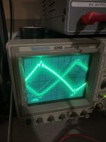
Probing speaker terminal scope shows negative DC build I believe (line jumps down a bit and rises to 0v repeatedly)
Relay clicks, no change
Passing 40hz signal through the amp, about 1/3 headunit volume (below 1/3 there is no change), amp protect light dimly lights, a buzzing begins near PS transformers and stays constant, speaker terminal changes into sawtooth wave and stops jumping
With no signal input the sawtooth wave is clear, gets blurry with signal, I assume the blurring is audio signal (both headunit volume and amp gain change blurring)
Stopping signal makes it clear again
Sawtooth peaks have some sort of wave on them (both with and without signal) picture provided
Changing subsonic pot makes the wave glitch out and the buzz near PS transformers turns to chirping
R7 is still removed
R70 is bridged over
Those 2 caps are still added
Attachments
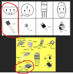
Those are wrong. If you want to know the pin configuration, use the datasheets for each component, not generic pin configuration.
Repost listing pins left to right (1, 2, 3) with the legs down and looking at the marked side of the transistor.
Repost listing pins left to right (1, 2, 3) with the legs down and looking at the marked side of the transistor.
Tried looking for the datasheets but I was not able to find any
Input Voltage: 14.52v
Q3
1: 0v
2: 14.49v
3: 0.51v
Q4
1: 0v
2: 2.14v
3: 0v
Q5
1: 0.51v
2: 13.94v
3: 2.17v
Q50
1: 2.21v
2: 0v
3: 7.23v
Input Voltage: 14.52v
Q3
1: 0v
2: 14.49v
3: 0.51v
Q4
1: 0v
2: 2.14v
3: 0v
Q5
1: 0.51v
2: 13.94v
3: 2.17v
Q50
1: 2.21v
2: 0v
3: 7.23v
I can understand for some but for the KSP2907a, the datasheets come up at the top of the search. The others may need a KT of 2S prefix.
If you remove C14, will the relay engage?
Q5 is also a bit suspicious. If the relay doesn't engage with C14 out of the circuit, pull it and check the junctions for forward voltage as well as leakage.
If you remove C14, will the relay engage?
Q5 is also a bit suspicious. If the relay doesn't engage with C14 out of the circuit, pull it and check the junctions for forward voltage as well as leakage.
If you don't know how to test for leakage and open junctions, simply repost the voltages with those two components out of the circuit.
You could also bridge the collector and emitter of Q3 to see if the relay will engage and to see if the amp produces audio. Connect the speaker after the amp is powered up and only after you've confirmed that there is no more than a tiny fraction of a volt DC across the speaker terminals.
If the amp is out of the sink, power up for only a few seconds at a time unless you're 100% sure that no semiconductors are heating up.
I can post new readings tomorrow
The amp produced audio a few days ago (after post #205) I connected a speaker to it and I tested it for about 30 minutes on a bunch of different songs and tones.
I did not run into any issues with it, however it did seem to lack quite a bit of power as it was somewhat quiet on a 30w 4 ohm speaker (I believe the amp is rated 1750w rms at 4 ohms 14v, could it be the protection issue limiting power?)
Headunit was as loud as I can get it before clipping and gain on the amp was on 3/4. I tested full gain for a couple of seconds and it would play, cut out, resume, cut out, and so on, still being quieter than I expected for all it could give.
I have a 10amp fuse on power terminal but I dont recall it pulling anywhere close to that
You were correct about the sawtooth being a higher frequency, I changed my scope settings and was able to see the 40hz wave
The DC on the speaker terminal is only in normal power
When the amp goes into half protect the DC build stops
Is there something on the test bench that's changing from when the amp plays and when it does not? Don't overlook any little thing.
Only things on the same outlet are the scope and 2 usb lights
I usually have one on at a time at random however I’m able to keep them off for testing in the future
Also a headunit on the same power supply though I noticed some internal corrosion on it so I’m using another headunit now and I’ll see how it does
I usually have one on at a time at random however I’m able to keep them off for testing in the future
Also a headunit on the same power supply though I noticed some internal corrosion on it so I’m using another headunit now and I’ll see how it does
Input: 14.58v
Q3
1: 0v
2: 14.57v (engaged then disengaged once while probing, might have bridged a leg accidentally though I don't believe I did)
3: 0v
Q4
1: 0v
2: 7.79v
3: 0v
Q5
1: 0v
2: 14.24v
3: 7.79v
Q50
1: 7.79v
2: 0v
3: 7.25
I also put deoxit on all pots and the switch as they were pretty dirty and I was having the weird issue with the subsonic pot
Not sure if it did anything but thought it may be helpful?
Do you have spare resistors, something in the 100k area?
If so, replace R10 with a 100k, replace C14 and Q5. Does the relay engage.
If so, replace R10 with a 100k, replace C14 and Q5. Does the relay engage.
- Home
- General Interest
- Car Audio
- 2 Monoblock Class Ds Not Working, I'm Lost

