I can build ANYTHING, but not so good with maths. I've looked at both of these spreadsheets and can't find anywhere to indicate what low freq rolloff I am looking for. Any help is greatly appreciated.
Found them.
Here are the two spreadsheets I used.
https://dl.dropboxusercontent.com/u/1444609/diyaudio/2013/Geddes.xls
https://dl.dropboxusercontent.com/u/1444609/diyaudio/2013/OS%20WG%202.xls
All credit goes to their creators (which I think are named within)
OS waveguides are really simple. It's basically two steps:
1) What coverage angle do you want? 90 degrees? 60 degrees? 45 degrees?
2) How low do you want the coverage? 1khz? 2khz? 500hz?
If you know those two things, they'll determine the width and depth of the waveguide. The width of the waveguide will be dictated by question two. For instance if you want to go down to 1000hz you want a waveguide that's 34cm wide. (Speed of sound / frequency) = (34000 cm per second / 1000) = 34cm
The depth of the waveguide can be determined by using a right triangle calculator. For instance, with ninety degrees of coverage the waveguide will consist of two right triangles, with angles of 90, 45 and 45. The width of the base of the triangle is 17cm and the depth of the triangle is 17cm. Put those two triangles together and you get a mouth of 34cm and a depth of 17cm and a coverage of 90 degrees.
All of this is complicated by the fact that the throat is 1" in diameter. So pop the numbers into hornresp and tweak away. Hornresp can help you make a mold too, just check out the instructions that come with it. (Hint, it's the 'export' function from the frequency response page.)
Geddes more or less dismisses the concept of cutoff. Read his Audioexpress interview for why that is.
Thanks Patrick. so there is no special rounding coordinates in the first curve of the throat?
I will turn these out of wood so no mold necessary.
I would use my JBL 2441 2" compression drivers. How does that change things.
I will turn these out of wood so no mold necessary.
I would use my JBL 2441 2" compression drivers. How does that change things.
Last edited:
So you think some of these problems could be overcome by running a larger waveguide and larger compression driver, and crossing lower say 600hz?
So you think some of these problems could be overcome by running a larger waveguide and larger compression driver, and crossing lower say 600hz?
No, the exact opposite.
Do you have a large room? If so, use a large waveguide.
Do you have a medium sized room? If so, use a medium size waveguide.
The use of a large waveguide in a medium sized room makes the problem worse, not better.
I think that this is a phenomenon that most people aren't accustomed to, because most people have never listened to a speaker where the gap between the tweeter and the midrange is nearly half a meter! That's a big gap!
As far as crossover point goes, that's going to be dictated by the gap. You'll want to use a multiple of the gap. With a 38cm gap between woofer and tweeter that means you'll want to use one of these frequencies:
894hz
447hz
223hz
Obviously, you can't get a 1" compression driver down to 447hz, or 223hz, so that leaves one option for crossover frequency.
Thanks for the concise lesson, dipped my toe into the Gedlee thread and got lost pretty quicl
Room is about 6m x 6m, pretty large for english standards. Most of the listening take place on the sofa against one side wall though, not ideal.
I love my full range (Mark Audio Alpair 7.3's) Just wanting to experiment with other types of speakers.
As all my systems are active, Could the horn overlap the woofer? or perhaps in a similar way to the KEF Moun, have two side firing ones so they occupy the same vertical plane?
Hi dennis, I believe the skill lies in making the exit angle of the CD meet up with the waveguides walls in a smooth manor, I managed to get one of the spreadsheets to print out a profile I could pin up behind my lathe.
How do you plan on turning 15", I presume not from solid?
How do you plan on turning 15", I presume not from solid?
Thanks Patrick. so there is no special rounding coordinates in the first curve of the throat?
I will turn these out of wood so no mold necessary.
I would use my JBL 2441 2" compression drivers. How does that change things.
I can't think of a single good reason to use a 2" compression driver.
The first inch of the OSWG, or any horn for that matter, is insanely important. If you're off by five millimeters it makes a difference. Heck a single millimeter matters at 10khz.
Due to that, if I were going to make the horn out of wood, I'd look at a couple options:
1) The first option is to make the first inch independent of the rest of the waveguide, and then glue it together. For instance you could use five sheets of five millimeter MDF, and cut each of those five layers on a drill press. The use of a drill press and hole saws will give you a perfectly round and a perfectly accurate throat.
2) Second option is to make the throat to small, then drill it out with a drill bit, and then file it down. This option isn't as accurate, but it's way better than using a conical horn. Basically you make the throat about 30% too small, then drill straight down the middle, then file. For a 1" compression driver this means making a 0.707" throat, then drilling it out with a 1" bit.
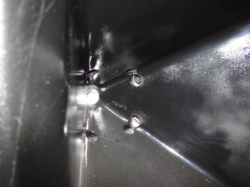
End result looks kinda like this
The purpose of using a waveguide is provide controlled dispersion.As far as crossover point goes, that's going to be dictated by the gap. You'll want to use a multiple of the gap. With a 38cm gap between woofer and tweeter that means you'll want to use one of these frequencies:
894hz
447hz
223hz
Why would you want to use anything other than the frequency that the woofer dispersion matches the waveguide dispersion for a crossover frequency?
The purpose of using a waveguide is provide controlled dispersion.
Why would you want to use anything other than the frequency that the woofer dispersion matches the waveguide dispersion for a crossover frequency?
A lower crossover point from waveguide to woofer will improve the off axis frequency response at the expense of output. For instance at 38cm waveguide and 38cm woofer with a center to center spacing of 38cm will have similar directivity at 894hz. (38cm.)
As you move off axis you'll get nulls, particularly above the crossover frequency. This is because of the pathlength difference.
Lowering the crossover frequency reduces the difference in pathlength, expressed in wavelengths, between the tweeter and the midrange.
For instance if you use a crossover frequency of 900hz and you move your head 19cm above the listening axis, the pathelength difference is one half wavelength at the crossover frequency. OTOH if you use a crossover frequency of 450hz and you move your head 19cm above the listening axis, the pathlength difference is 1/4wl at the crossover frequency.
And THAT is why lowering the xover point improves the off-axis response.
I modeled this behavior in my thread named 'Monster Massive." And it's not as simple as pathlength, you also have to factor in crossover slope and phase.
An externally hosted image should be here but it was not working when we last tested it.
Or, you know, you could just use a coaxial and not sweat the pathlength difference.
1) A waveguide can be made with a wide variety of dispersion angles.1)A lower crossover point from waveguide to woofer will improve the off axis frequency response at the expense of output. For instance at 38cm waveguide and 38cm woofer with a center to center spacing of 38cm will have similar directivity at 894hz. (38cm.)
2)As you move off axis you'll get nulls, particularly above the crossover frequency. This is because of the pathlength difference.
3)Lowering the crossover frequency reduces the difference in pathlength, expressed in wavelengths, between the tweeter and the midrange.
For instance if you use a crossover frequency of 900hz and you move your head 19cm above the listening axis, the pathelength difference is one half wavelength at the crossover frequency. OTOH if you use a crossover frequency of 450hz and you move your head 19cm above the listening axis, the pathlength difference is 1/4wl at the crossover frequency.
And THAT is why lowering the xover point improves the off-axis response.
There is no guarantee it will match a the dispersion of a particular woofer at a specific frequency unless you measure the specific woofer. Your example is not real-world.
2) Off axis vertically, yes. Most people listen at a fixed height, and it is easy to position the loudspeaker so one is on axis between the center of the woofer and waveguide, in which case the c to c distance is not very crucial.
3) A good argument for using 3" or 4" diaphragm drivers that are capable of lower crossover points.
At any rate, the dispersion patterns of an open baffle 15" is so odd when combined with a waveguide that all this is academic.
1) A waveguide can be made with a wide variety of dispersion angles.
There is no guarantee it will match a the dispersion of a particular woofer at a specific frequency unless you measure the specific woofer. Your example is not real-world.
2) Off axis vertically, yes. Most people listen at a fixed height, and it is easy to position the loudspeaker so one is on axis between the center of the woofer and waveguide, in which case the c to c distance is not very crucial.
3) A good argument for using 3" or 4" diaphragm drivers that are capable of lower crossover points.
At any rate, the dispersion patterns of an open baffle 15" is so odd when combined with a waveguide that all this is academic.


For my dipole I was going to follow the lead of John Kreskovsky. Kreskovsky uses a spacing of about one half wavelength. For instance in the NAO Note II the crossover from midrange to midwoofer happens at 1khz, and the spacing is about 17cm.
The Summa is a monopole and uses a spacing of one wavelength.
The NAO Note II is a dipole, and due to that we have to consider both the directivity and the frequency response, in particular the dipole peak that occurs when the rear sums in-phase with the front.
Based on this criteria, if I had a 15" waveguide and a 15" woofer I'd be looking to do a crossover at 450hz.
Obviously if one follows this criteria, than one has to use either a coax above the woofer, or shrink the woofer. If one dropped the waveguide down to 8" and used an 8" woofer in a dipole one might be able to get away with a crossover of 844hz.
Of course all of this is coming from someone that hasn't finished their waveguide/dipole project, and is simply copying what Kreskovsky did.
And posting simulations that have little bearing on what goes on in a real room 😉.Of course all of this is coming from someone that hasn't finished their waveguide/dipole project, and is simply copying what Kreskovsky did.
Well, considering a pair of open baffle Alpha 15 can do around 90 dB at 40 Hz in room, and a decent 15 in boxs can do 120 dB, you would need about 64 of them.
Wait, the baffle would be huge, so you could get by with perhaps half or 1/4 that amount.
You recently stated:
"Design goals are to try and integrate a large (12-18") OSWG into an attractive speaker."
Do you have any sonic goals for the speaker?
After reading a bit more, Alpha's seem to be ok, for the low end, below 200Hz, and not great after that.
This is an experiment in design, and first and foremost about building horns/waveguides.
Id love to own a pair of Gedlee Summa's, but can't afford them or afford their floorspace. As a cabinet maker& designer, I have the requisite skills to make something similar and perhaps more beautiful for little more than my time.
I have yet to see someone implement OSWG on an OB. So the first goal is deciding on a waveguide size, I remember reading a post by Gedlee stating the 18" is the optimum size (for his DE250) but that manufacturing and shipping constraints can't justify the few extra inches.
So sonically the goals are to integrate a OSWG waveguide into baffle, semi seamlessly (turned oak, oak baffle). Has to handle music and movies, happy to have a sub/subs. Never too loud, making do with Alpair 7.3's in standmount boxes. I have never hear OB, and so can't comment on their characteristics, but I have a few parts lying around (some BMS CD's, a pair of betsy's, peerless mids, and a few other bits) perhaps I should put them on a baffle and see.
I have 8 channels of active XO and 8 channels of power amp, 50wpc to play with, and a tiny budget!
you could combine the OSWG with a closed high quality woofer like the mummy, or make a 3way OB crossing over to a 8" mid with good dispersion.
Can you side mount mid drivers and have two magnets attached situated in the void behind the waveguide?
As a matter of fact, this is the case for the comparison between Alpha15 and A&D R1524: OB Sanity Check - Focal Car Speakers
/Erling
/Erling
- Status
- Not open for further replies.
- Home
- Loudspeakers
- Multi-Way
- 15" OSWG & 15" OB 4 ME