Good explanation
Federico,
Thanks for the very good explanation and examples. By the way, I was only complaining about study in the usual student way. I took my circuit books with me when I went to do errands so that I could start to refresh my very rusty memory.
In case two, is it possible that the pot balances rather than unbalances the circuit, that is makes up for slight mismatches in the tubes two sections?
Much to think about,
Michael
In case two, is it possible that the pot balances rather than unbalances the circuit, that is makes up for slight mismatches in the tubes two sections?
Yes, sure, Michael
I apologize
In my mind I was thinking at the perfect circuit that
is obviously balanced and the pot will unbalance it.
But in the real world the circuit is unbalanced and
the pot will balance it. It is the reason to put a pot
there.
The conclusion is that circuit (2) (anode choke ) can be balanced by a pot while cir (3) (cath choke) no.
Federico
Hi Michael, All
I have tried the following simulated experiments to put in evidence third order harmonic cancellation due to intermodulation.
The following is a simplified version of your output stage, Michael.
At first I feed it with two ideal (1kHz, 20 Vrms) generators V1 and V2, with opposite polarity.
power is about 3W
I obtain the following result
H2………0.02%
H3………3.0%
H4………0.005%
H5………0.3%
Htot……3.2%
Then I added two generators (2kHz, 1.27 Vrms) V3 and V4 in phase ( but each shifted pi/2 in respect to V1) to simulate 2nd order harmonic distortion from the driver (as in anode choke case). The value 1.27 Vrms has been manually optimized.
Results are:
H2………0.007%
H3………0.01%
H4………0.002%
H5………0.14%
Htot……0.15%
The cancellation phenomenon is evident for H3. So, since to cancel a 3kHz signal another 3k signal is needed I think that it is generated by intermodulation from 1k and 2k signals.
The following post about optimization of your circuit
Bye
Federico
Attachments

Model results
Hi Federico,
Excellent work and interesting results. Do you think the intermodulation distortion that is necessary to cancel the 3rd harmonic will result in a disagreeable amount of intermodulation distortion at the output? As hard as it has been to find any information about harmonic distortion levels to be expected in non-feedback PP amplifiers, it is even harder to find mention of IMD. May I ask what sorts of numbers you have measured or modeled in your own work? Now truly, I listen to this amplifier extensively as I experiment with it and I think it sounds very good. In the absence of 10 or 20 pairs of other ears to listen and give opinions on it, I rely to some degree on the idea that if I think it sounds good and the distortion numbers are minimized, that most other ears will agree it sounds great.
It will be very interesting to hear about the results of your optimization attempts. I have found in my experiments that when the distortion is minimized at one output level and then the output level is changed, up or down, distortion may be far from the minimum that can be found for that level. In my mind I have likened it to canoeing on a somewhat curvy river or hiking at the bottom of a twisting canyon. When you are in the middle of the river or the center of the canyon you are at the minimum. As you move in a straight line from that point to another you may run into the bank or have to climb the canyon wall to maintain your line. This has required choosing points that are not the absolute minimum available, but rather those that allow a sight line that requires the smallest excursions up the wall of the canyon on the entire trip from lowest power to highest. Understand what I mean?
My work has become more serious since yesterday because I found out that the person for whom I am to build an amplifier, which I why I started working on this design in the first place, has made the decision to proceed and ordered the Lundahl transformers for the project. This means that now I must make the decision as to whether this is a viable front end to drive 2A3 or 300B or some other still to be decided output tube. Or if it should be abandoned for some other plan.
Thanks again for all you efforts,
Michael
I have found in my experiments that when the distortion is minimized at one output level and then the output level is changed, up or down, distortion may be far from the minimum that can be found for that level.
Yes, true
Infact I am experimenting troubles in finding optimum
conditions.
so, I cannot be very helpful to you.
However try, if you want, these things:
3rd order cancellation is important only at high level
since, lowering the level, 3rd order dist intrinsically decrease much
then 2nd order. So at low level the driver will provide
too much 2nd order and hence cancellation wll not happen.
To decrease distorsion I, at first, advise you to increase the current in the driver by changing the value of the anode resistor
from 22k to 12k.
If things work as I think distortion will decrease at low level
and increase at high level.
Then you have to decrease the value of the driver bias resistor from 800 to, say, 400 with steps of 50 Ohm (this is an attempt to increase 2nd order[of driver] at high level and thus minimize 3rd order output).
Look both at low level and high level distortion ( total dist).
If I am right dist will decrease at high level and increase at low level. At some point you will have less distortion at both levels.
let me know
Federico
Will try
Hi Federico,
First your opinion, do you think this circuit can be bettered by other simple designs? Suggestions? What output would your model show if the OPT was changed from 8.4k to 40k, as with an interstage?
I have one more brief experiment I want to try with the 5687 cascode and then I will put the 6SN7 back and try your suggestions.
I did collect data back in January with a 10k Rp on the 6SN7. I did not graph it until today after you suggested where to search for new conditions. I present it now for your inspection. I am not sure how much optimization I performed before collecting this, it was a long time ago by the standards of my memory (not so good). Probably I did some work here though.
The DC conditions I have recorded at: B+=254V, 12B4 plate=249V, 12B4 Vb=28.66V, 6SN7 Vp=150V, 6SN7 Vb=3.3V, 6SN7 Rk~225 ohms, 12B4 Rk not recorded.
Thanks,
Michael
Attachments
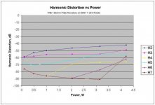
hi
from the pic it seems that the cir is not well balanced (2nd
harm too big). However I think they are good results.
The working point of the opt stage appear good and
also the trafo. IMHO 40k will not work: to mantain power
the static point is to be changed toward higher voltage
and lower current in a strongly non linear zone. Also
in this way I suspect early clipping.
Instead you can try to reduce to 5k and have more power,
maybe somethig less of 6W.
I think your project is simple and good.
I will spend time in tuning it rather than in experimenting
new driver stages.
Obviously with 2a3 or 300b both power and quality will
increase. But this is another moovie.
Federico
Designs
Hi Federico, anyone else still with us,
Remembering that this is two projects in one. The reason for the design in the first place was as a volt amp and driver stage for another tube, the second came because I liked the sound while experimenting with a regular output transformer as a stand in for the interstage. And since I have been thinking to build an all in one home theater amp, why not this one.
On the subject of the first, I collected data a couple of weeks ago with the load on the secondary being a 100 ohm resistor on the 16 ohm tap. This was in the hopes that at 1kHz it would act somewhat like a high impedance interstage. I submit the graph for your study. I did use higher B+ at 314V with Vp=303V, Vb=-36.8V and Ip=21mA. Admittedly, this is running the 12B4 absolutely flat out max dissipation. Maximum power out was 1.2W, just to mention it. Also indicated in my notes was that this was at a pk-pk output of ~400V on the 12B4 plates. Do you think there is any validity to data collected with such a load on the secondary? I thought until just now that the Rp of the 6SN7 was 10k, but rereading the data I am not sure of that. Also, I had two 10H, 75 ohm chokes in series with the OPT CT with the ultrapath cap of the 12B4 loacated from CT to top of Rk as usual. Will have to retry this experiment with the 10k Rp and no 10H chokes if you think the approach will offer reasonable data.
On the subject of the second, since I will have to purchase transformers for the amplifier, do you think 5k would be preferable to 8-10k? My speakers are quite efficient so I don't necessarily need to maximize power output.
I have replaced the cascode with the 6SN7 and am preparing to do a little listening and data collection.
Thanks again,
Michael
Attachments

Remembering that this is two projects in one
I had forgotten it.
Do you think there is any validity to data collected with such a load on the secondary?
Yes, if intended to emulate an interstage trafo.
My speakers are quite efficient so I don't necessarily need to maximize power output.
If you don’t need power then 8-10k is better for distortion and damping factor.
I go home
Bye
Federico
Reading material
Federico,
Could you point me to any reading material that treats the loop currents and mathmatical description thereof? On the web would be great, but any references would be appreciated.
Thanks,
Michael
Federico,
Could you point me to any reading material that treats the loop currents and mathmatical description thereof? On the web would be great, but any references would be appreciated.
Thanks,
Michael
Sorry,
Never read anything specific about current loops
like those in your cir. However Mr. Broskie
at http://www.tubecad.com/index_files/page0039.htm often adopt the current path perspective in
analyzing circuits.
Federico
Never read anything specific about current loops
like those in your cir. However Mr. Broskie
at http://www.tubecad.com/index_files/page0039.htm often adopt the current path perspective in
analyzing circuits.
Federico
Semi-optimized 10k Rp data
Hi Federico,
I collected some data this morning for semi-optimized conditions with the 10k Rp on the 6SN7. Again at these conditions I am running the 12B4 flat out. I don't know how much I can cut it back yet. Haven't had a chance to listen yet either, too early for the neighbors. When I was listening yesterday under some unoptimized condition it seemed a little bass shy from what I remembered. Haven't looked at frequency response yet either.
If you are interested (and even if you are not) here are the
DC conditions: B+=264.5V 12B4 plate=259V 12B4 Vb=-31.0 12B4 Rk=610 ohm 6SN7 plate=146V 6SN7 Vb=-2.8 6SN7 Rk=188 ohms
Michael
Attachments
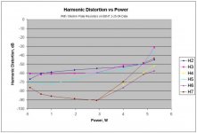
Hi Michael
It is good for me.
however, I obtain better results wth 400-500 Ohm for 6sn7 Rk.
Way don't you put a 1k pot as Rk? and try to optimize on the fly?
P.S. I forget, I have to thank you so much
Michael, your cir gives me the opportunity
to study in deep P-P cir and driver.
I have learned many things during these days.
Thank you again.
Glad you enjoyed it
Hi Federico,
Glad you found this study interesting, I have enjoyed it as well.
I do have a 4W 10 turn 1k pot with reading dial for the Rk of the 6SN7. It is extremely convenient for the breadboard. I also have a 1500 ohm rheostat for the 12B4 Rk and a Heathkit variable supply 0-400V at 100mA for power. Makes a very versatile setup.
I tried briefly looking at higher Rk for the 6SN7 when arriving at these conditions and 3rd harmonic, which is the only one I was looking at, just kept going up. Maybe I didn't get high enough to find another minima. Did your model show a linear decrease with increasing Rk or a new area of minimum around 4-500 ohms? Am listening quietly now, so will try looking in a bit.
Michael
Yes
I am observing a minimum zone around 400-500 Ohm
/other things constant with values from your last post/
Really, things are a bit more complicated since what
is good at low level is not so good at high level and
vice-versa.
4-500 ohm is a good compromise. This in my sim.
You may find other values but, in every case, a minimum
zone does exist, at least I think.
federico
any other suggestions?
Federico, All,
Haven't tried the Rk change yet, but thought I would ask. Any other suggestions for changes to the circuit to try out? The Lundahl input and interstage transformers are supposed to arrive today, so I will get to see if my work translates also
Does the spice you use have an optimize algorithm or would a person have to collect the outputs for different conditions of the independant variables and then transfer that to another program to do software optimization?
Just wondering,
Michael
Oh-Oh
Federico,
Help I'm falling, aaaAAh. With the 10k plate resistors this circuit seems to be very sensitive to changes in Rk. That may be why I abandoned it earlier and went back to 22k. Small changes in Rk yield radically different distortion profiles and the minimums for each order do not show good overlap. Also, the nulls are very deep, but very narrow. This makes me worry about the long term stability when tube aging is added into the equation.
The data I presented yesterday may have been very near the best I can do if minimizing the higher orders is the goal. I did find a minimum in H5 at around 450 ohms Rk (dial reading, must add in the 50 ohm pot), but H3 was huge at any value above ~220 ohms. I did note that the best mix seems to occur in the area where the gain (mu?) of the 6SN7 is at it's maximum.
Maybe I should try 12k Rp?
Michael
Hi Michael
Sorry for what happening
Increase Rp, Try 12k then 15k in such a way
to avoid the erratic behavior.
The professional version of my software ( Micro Cap 7)
do optimization. That is you specify the parameters
( e.g., rk,rp etc ) specify what to minimize or max
(e.g. thd or 5th harm, etc ) and it find the minimum.
But pro version is at about 6000 euros
( 2000 for university) so I use the demo version
which is limited to 50 components and has
not some features like the optimization.
But I can use the step function:I chose the
parameters, the function (eg. THD) and the soft
step them and tell me the results. It is a by trial
procedure.
Why don't you download a free demo
at
http://www.spectrum-soft.com/demodown.shtm
Good luck
Federico
Lundahls
Federico,
Will try the spice. Have had a hard time motivating myself in the past to learn it though.
I got the Lundahls transformers yesterday. I hooked up the 1676 input as the phase splitter in place of the UTC A-11 and the 1660S/PP in place of the Bell output. I have some square wave issues with both of them, but harmonic distortion preliminaries look very good indeed.
I haven't written any results yet, but if I recall correctly at 50Vrms out (60k load on each half of secondary, voltage read across one half) all orders were in the magnitude of my generator distortion and at 127Vrms 7th order was -62dB and everything else =>-70dB below the fundamental. Now I just have to decide on the output tubes!! Any suggestions?
Michael
Excellent results !
However the best are direct heating triodes
Their plate curves are the more linear.
Choose basing on power and money.
Federico
Dependssuggestions
However the best are direct heating triodes
Their plate curves are the more linear.
Choose basing on power and money.
Federico
- Status
- Not open for further replies.
- Home
- Amplifiers
- Tubes / Valves
- 12B4A PP schematic