analyzer impedance etc
EC8010,
Thanks for the test methods. I guess if I had dusted off my brain I knew how to do the unbalanced case, but had never considered the balanced case. It may prove handy in the future.
The analyzer I am using is an HP 302A. I think it was introduced in 1959 and is an all solid state design. It seems to work quite well, that is it's readings for low distortion signals seem to be in good agreement with my DVM and quantitation by o-scope. I'm quite happy with my $10 buy. It is huge though.
Today when I tried attaching it on the grid of the 12B4 I found a large voltage drop (8.2V ->7.5V) at the output and severe distortion in the sine wave at the output. That hadn't happened before and I am unsure if it was a circuit change that caused it. Could it be the increased 6SN7 output AC impedance caused by having the 15H choke in the cathode circuit? Although I didn't notice it yesterday. I used a 10Mohm scope probe to circumvent the loss, although I suppose this brings it's own problems at higher frequencies. Doh, the large drop and distortion occured when I had the 75H choke in the anode circuit and the 15H choke in the cathode circuit. I don't think I had tried measuring that configuration at the 12B4 grid before. Which brings me to results for that test.
With 75H and 15H
12B4 grid....................OPT sec
21.0V..........................8.0V
50mV..........................21.5mV
74mV..........................167mV
With 75H choke and no 15H choke, ie conditions tested before
12B4 grid...................OPT sec
22.3V.........................8.0V
780mV.......................1.4mV
60mV.........................48mV
Does this further muddy the waters?
Michael
5687 cascode
Just for the heck of it I replaced the 6SN7 differential stage with a 5687 cascode today. Don't you just love a breadboard. Well the 5687 doesn't appear to be quite as breadboard friendly as the SN7. Have a few noise and oscillation problems and couldn't get it to settle down as a differential at all. Once I sort of tuned in though I gave it a listen and it seems an alright stage. Maybe will get a little more serious about it tomorrow.
Michael
I'm not clear as to why you have a choke in both the anode and cathode circuits. Are you trying to make a phase splitter? A diagram would help greatly.
Be wary when connecting test equipment around grids and cathodes. Your HP may be transformer coupled, in which case its input is a short circuit to DC and may be upsetting DC conditions. Similarly, audio tests sets tend to have quite high input capacitance, and that can make test circuits unstable, or at the very least, radically change their frequency response (which can affect distortion). I find it's a good idea to keep the oscilloscope on the output and check that connecting other equipment doesn't change the oscilloscope display.
Be wary when connecting test equipment around grids and cathodes. Your HP may be transformer coupled, in which case its input is a short circuit to DC and may be upsetting DC conditions. Similarly, audio tests sets tend to have quite high input capacitance, and that can make test circuits unstable, or at the very least, radically change their frequency response (which can affect distortion). I find it's a good idea to keep the oscilloscope on the output and check that connecting other equipment doesn't change the oscilloscope display.
chokes
EC8010,
There is a schematic further back in the thread and I haven't redrawn it to reflect every iteration I have tried. I am phase splitting with an input transformer. The 75H choke, which is in the anode circuit, but not properly an anode choke, has been shown in the collected data to have a salutory effect on the distortion levels at the output. The 15H choke in the cathode circuit showed better balance at the output of the 6SN7, but increased levels of distortion at the output of the amp. So why not try both, it's just a breadboard and a half hour experiment.
I read an excellent article recently on the value of breadboarding. It was aimed primarily at SS and RF circuits, but I think the advice holds. Once you have a breadboard, a circuit change is relatively trivial. Therefore, even if you don't have a well developed theory supporting the purpose and outcome of a circuit change, it is a minor task to implement it and actually see the results. Now surely they were not advocating random changes, but I had seen the results of each of these circuit adaptations separately. So why not combine them?
Good advice on the o-scope. I think it is not bad practice to have one connected at all times. It gives one a familiarity with both the planned and random outputs of the circuit and allows a more rational judgement on what are real effects and what is noise/background/faulty measurements.
Michael
Yup. Breadboarding is fun. You can even plug in different parts just to see what effect they have, and then develop a theory 😀
Tim
Tim
Speaking of the breadboard
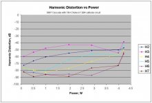
Yeah, they are handy. Here's some preliminary distortion measurements of a pair of 5687s in cascode as the voltage amp. NO choke around the anodes, but the 15H in the cathode of the 12B4 pair. Clipping seems to set in earlier and harder and I'm not sure why. Shouldn't be overdriving the 5687 grid. May not be near optimized, although I tried quite a few settings. Couldn't get differential to work well at all. May be too much mismatch in the tubes and I've only got a couple.
Sounds very nice but not at all sure it is as good as the 6SN7 with 75H choke
Michael
Attachments
Hi,
Just curious...Any particular reason for chosing a cascode configuration?
TA,😉
Here's some preliminary distortion measurements of a pair of 5687s in cascode as the voltage amp.
Just curious...Any particular reason for chosing a cascode configuration?
TA,😉
No particular place to go
Hi Frank,
Not really any reason. Had never heard one, had heard they can be very good and had a couple of 5687 that seemed suitable. So I tried it. Must admit it sounds pretty good, so I will probably give it a couple more days worth of effort, just to see what it can do.
Michael
Hi Frank,
Not really any reason. Had never heard one, had heard they can be very good and had a couple of 5687 that seemed suitable. So I tried it. Must admit it sounds pretty good, so I will probably give it a couple more days worth of effort, just to see what it can do.
Michael
Hi Michael,
The reason I asked is that the cascode can easily be compared to a penthode; it has almost the gain of it, distortion characteristics to go with it...
In short it behaves like a penthode minus the noise.
This in combination with the super linear curves of the 12B4As seemed really odd to me.
Mind you, that doesn't mean it won't or can't sound good...It just draws the attention, that's all...
Have fun,😉
Understood
Hi Frank,
I understand some of the potential problems with this configuration, though certainly not all of them. Given the constraints I placed on the operating conditions, the gain modeled at something around 20, didn't actually measure it yet. The distortion profile I posted above show a dominance of 3rd and 2nd, with 5th being lower in proportion than it was in the 6SN7 data I posted in post #9. But then again, what else was I doing on a weekend?
Michael
Hi,
There are of course several tyes of cascode circuits but from reading your experience, one possible cause of problems is that you may have exceeded the cathode to heater insulation of the top triode.
This can manifiest itself as wild oscillation and HF noise, srceachy sounds that can take out tweetrers within seconds, amongst others.
Are you sure the gain was modeled as 20, not 200?
Dare I even ask?😀
Cheers,😉
There are of course several tyes of cascode circuits but from reading your experience, one possible cause of problems is that you may have exceeded the cathode to heater insulation of the top triode.
This can manifiest itself as wild oscillation and HF noise, srceachy sounds that can take out tweetrers within seconds, amongst others.
Are you sure the gain was modeled as 20, not 200?
But then again, what else was I doing on a weekend?
Dare I even ask?😀
Cheers,😉
low voltage
The upper cathode is at 80V. The B+ is 270V. TubeCad said gain of 20, don't really think it can be much more given it's performance in circuit. The oscillation was cured by tube shields and a little tightening up of the wiring on the breadboard.
Michael
The upper cathode is at 80V. The B+ is 270V. TubeCad said gain of 20, don't really think it can be much more given it's performance in circuit. The oscillation was cured by tube shields and a little tightening up of the wiring on the breadboard.
Michael
Hi,
That's possible, gain depends on a number of parameters here, the load you're trying to drive will probably reduce it to the figure of 20.
The no load gain however should be much higher than that:
(plate load X (ma per volt) ) / 1000
Need to catch some sleep now...😉
TubeCad said gain of 20, don't really think it can be much more given it's performance in circuit.
That's possible, gain depends on a number of parameters here, the load you're trying to drive will probably reduce it to the figure of 20.
The no load gain however should be much higher than that:
(plate load X (ma per volt) ) / 1000
Need to catch some sleep now...😉
Hi Michael, All
I was very busy during these last days.
However I made a lot of stimulating study about your circuit.
It certainly is a perfect one to investigate on and to learn a lot of
things.
I changed a bit the model of my 6sn7 since my results were too
much distorted in respect to yours. I think the reason may be one of
the following two:
1) your 6sn7 are high quality tubes while my model refers to worse tubes.
2) due to some reason ( input transformer or too low input impedance) the input
of 6sn7 is distorted and cancels some intrinsic distortion of the tube resulting
in a better performance.
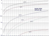
However the result in this new condition are:
Anode choke Vk=5.62, Vp=169
12B4 grid...................OPT sec
22.3V.........................8.0V
654mV.......................(0.74mV)
86mV.........................61mV
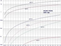
Anode choke with ultrapath cap
12B4 grid...................OPT sec
22.3V.........................8.0V
442mV.......................(0.84mV)
69mV.........................96mV
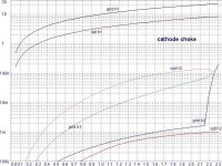
catho. choke Vk=5.97, Vp=179
(reduced input to avoid clipping)
12B4 grid...................OPT sec
21.7V.........................8.0V
19mV.......................(1.0mV)
79mV........................134mV
in agree (qualitatively at least) with yours.
I have some problem since I noticed to be very near clipping conditions
This is to be avoided. Thus I repeated sim with variable input.
I obtained these pics. Attention: left axes is in Vrms while orizzontal axes reports 6sn7 input amplitude (not rms but (Vpk-pk)/2).
I am very satisfied of these results since they agree with my hypothesis.
Bye
Federico
I was very busy during these last days.
However I made a lot of stimulating study about your circuit.
It certainly is a perfect one to investigate on and to learn a lot of
things.
I changed a bit the model of my 6sn7 since my results were too
much distorted in respect to yours. I think the reason may be one of
the following two:
1) your 6sn7 are high quality tubes while my model refers to worse tubes.
2) due to some reason ( input transformer or too low input impedance) the input
of 6sn7 is distorted and cancels some intrinsic distortion of the tube resulting
in a better performance.
However the result in this new condition are:
Anode choke Vk=5.62, Vp=169
12B4 grid...................OPT sec
22.3V.........................8.0V
654mV.......................(0.74mV)
86mV.........................61mV
Anode choke with ultrapath cap
12B4 grid...................OPT sec
22.3V.........................8.0V
442mV.......................(0.84mV)
69mV.........................96mV
catho. choke Vk=5.97, Vp=179
(reduced input to avoid clipping)
12B4 grid...................OPT sec
21.7V.........................8.0V
19mV.......................(1.0mV)
79mV........................134mV
in agree (qualitatively at least) with yours.
I have some problem since I noticed to be very near clipping conditions
This is to be avoided. Thus I repeated sim with variable input.
I obtained these pics. Attention: left axes is in Vrms while orizzontal axes reports 6sn7 input amplitude (not rms but (Vpk-pk)/2).
I am very satisfied of these results since they agree with my hypothesis.
Bye
Federico
Attachments
Very Interesting
Federico,
Results and model predictions seem to be in pretty good agreement now. Nice work on the modeling.
Can you now take the case of anode choke, no cap, no cathode choke and predict an operating point (B+, 6SN7 bias, etc) that will give a minimum of odd order distortion?
Also, any other conditions I should test? I changed the front end to a cascode over the weekend, but it can be put right in ~10 minutes.
Thanks,
Michael
The choke issue - A little of theory
Hi Michael, All
A little of theory before facing to the optimization.
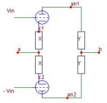
Consider the drive circuit reported in the figure, where Vin is the usual sinusoidal signal and, together with –Vin, it is the only independent signal source.
If for some reason (the presence of a current source or a choke), it is not possible for the current to flow toward node (a) or node (b), then, current will flow in the loop made by the two tubes and the depicted four elements and it can be mathematically shown that CURRENT will have only odd harmonics.
As a consequence of this V(an1,an2) and V(c1,c2) will have only odd harms.
If ,in addition, (b) is at ground for AC then V(an1) will have only odd harm and and V(an2) too.
If, instead, node (a) is at ground for AC, V(c1) and V(c2) will have only odd harms.
This irrespective of what the four elements depicted actually are.
Think about this.
Hi Michael, All
A little of theory before facing to the optimization.
Consider the drive circuit reported in the figure, where Vin is the usual sinusoidal signal and, together with –Vin, it is the only independent signal source.
If for some reason (the presence of a current source or a choke), it is not possible for the current to flow toward node (a) or node (b), then, current will flow in the loop made by the two tubes and the depicted four elements and it can be mathematically shown that CURRENT will have only odd harmonics.
As a consequence of this V(an1,an2) and V(c1,c2) will have only odd harms.
If ,in addition, (b) is at ground for AC then V(an1) will have only odd harm and and V(an2) too.
If, instead, node (a) is at ground for AC, V(c1) and V(c2) will have only odd harms.
This irrespective of what the four elements depicted actually are.
Think about this.
Attachments
OK
Hi Federico,
Are you a professor, intent on making me do my homework? Ok, Ok, I will pull out my Circuits 100 and see if I can make sense of it.
I can only think that if b is not at AC ground and a is, then the odd harmonic current will not appear at the output. The loop current confuses me. Time to study I guess.
Michael
back to the real circuit
Excuse me, Michael
My intent was to focus your attention on the peculiar behavior of this circuit that, definitely, is not so simple as I believed last week.
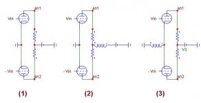
Consider circuit #1 (I have used fixed bias to simplify things). It is the classic driver stage for PP output. One tube does not see the other. The output at an1 or an2 is perfectly single ended. This
Situation is similar to the presence of an ultrapath capacitor: current is not constrained to circulate in a loop.
In case (2) and (3) current flows in a loop due to the presence of the choke.
In case (3) the balance between (an1) and (an2) is provided by the value of the two resistors: if they are equal the V(an1) will be equal and opposite to V(an2) and they both does not contain even order harms.
It is not possible to influence this situation by means of a pot. in the cathode. Voltages are always balanced, since the reference ( zero AC volts) is between the two res. Yes, it is possible that unbalancing the cath. pot some amount of even order harm will appear in the current, but very little with a 50 Ohm pot.
Always in case (3) the cathode of the tube(s) oscillates a little at a frequency double than the fundamental. Signal at cathode have only even harm.
In case (2) V(an1) and V(an2) are balanced only in the sense that V(an1,an2) have only odd harmonics, this is important because means that even order harm will be cancelled in the following
push-pull stage. However V(an1) do have even order harm, opposite to the previous case (3).
The point in common to choke and resistors will oscillate as the cathode of the previous case (3).
A pot in the cathode will have a greater effect that in previous case since it will unbalance the path toward the reference that now is at the cathode. Unbalancing the pot will change the amplitude of
V(an1) and V(an2): the fundamentals amplitudes will be no more equal.
As you see, the behavior of the pot follows from the analysis.
Bye
Federico
Excuse me, Michael
My intent was to focus your attention on the peculiar behavior of this circuit that, definitely, is not so simple as I believed last week.
Consider circuit #1 (I have used fixed bias to simplify things). It is the classic driver stage for PP output. One tube does not see the other. The output at an1 or an2 is perfectly single ended. This
Situation is similar to the presence of an ultrapath capacitor: current is not constrained to circulate in a loop.
In case (2) and (3) current flows in a loop due to the presence of the choke.
In case (3) the balance between (an1) and (an2) is provided by the value of the two resistors: if they are equal the V(an1) will be equal and opposite to V(an2) and they both does not contain even order harms.
It is not possible to influence this situation by means of a pot. in the cathode. Voltages are always balanced, since the reference ( zero AC volts) is between the two res. Yes, it is possible that unbalancing the cath. pot some amount of even order harm will appear in the current, but very little with a 50 Ohm pot.
Always in case (3) the cathode of the tube(s) oscillates a little at a frequency double than the fundamental. Signal at cathode have only even harm.
In case (2) V(an1) and V(an2) are balanced only in the sense that V(an1,an2) have only odd harmonics, this is important because means that even order harm will be cancelled in the following
push-pull stage. However V(an1) do have even order harm, opposite to the previous case (3).
The point in common to choke and resistors will oscillate as the cathode of the previous case (3).
A pot in the cathode will have a greater effect that in previous case since it will unbalance the path toward the reference that now is at the cathode. Unbalancing the pot will change the amplitude of
V(an1) and V(an2): the fundamentals amplitudes will be no more equal.
As you see, the behavior of the pot follows from the analysis.
Bye
Federico
Attachments
- Status
- Not open for further replies.
- Home
- Amplifiers
- Tubes / Valves
- 12B4A PP schematic