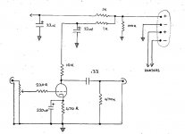
Also measure the voltage drop across the 10K anode resistor--it should be about 200V. If not, then you are not drawing any current and your cathode connection is probably the problem.
ok, pin 9 anode = 40V
across 10K anode resitor = 60V
B+ in = 110V
this was all with a 15K dropper resistor at psu end.
so in my small amount of wisdom i changed the dropper resistor to 6800 ohms
now i get pin 9 = 63V
across 10K anode resitor = 98V
B+ in = 171V
when i had the initial 10K dropper in i measured 330V before it, after was 110V so voltage across dropper was 220V, dropper was 10K so current was 14.6mA
do i have a problem with the current being drawn? I am reluctant to just keep reducing the dropper resistor in psu to increase voltage is there is another problem.
stuart
thanks to coffeedj for the support so far.
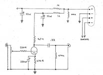
i have some new values but still small volume output. I have yet to test with my leak valve amp but whilst plugging the linestage between the output of my soundcard and some small active sony speakers that i use for computer sounds i still get vary little volume.
I have changed the dropper in the psu to 1K, also in the psu the 33K resistor to ground has been replaced by 100K.
The 10K anode resitor has been changed to 4K7.
My new voltages are slightly different on each channel but only by 3 or 4 volts.
B+ = 250V
Pin 9, anode = 144V
Before the anode resistor (4700 ohms) = 230V
I presume the voltage across the anode resitor is 230 - 144 = 86V.
Therefore, ohms law (i'm a newbie) makes the current across the anode resitor = 86/4700 = 18mA
I presume this will be the same current across the tube....
so why so shy on the volume?
Attachments

surfstu said:thanks to coffeedj for the support so far.
i have some new values but still small volume output. I have yet to test with my leak valve amp but whilst plugging the linestage between the output of my soundcard and some small active sony speakers that i use for computer sounds i still get vary little volume.
I have changed the dropper in the psu to 1K, also in the psu the 33K resistor to ground has been replaced by 100K.
The 10K anode resitor has been changed to 4K7.
My new voltages are slightly different on each channel but only by 3 or 4 volts.
B+ = 250V
Everything looks OK. You should get about 14dB of gain max. WHat is your input signal? What is the input impedance for the next stage?
Pin 9, anode = 144V
Before the anode resistor (4700 ohms) = 230V
I presume the voltage across the anode resitor is 230 - 144 = 86V.
Therefore, ohms law (i'm a newbie) makes the current across the anode resitor = 86/4700 = 18mA
I presume this will be the same current across the tube....
so why so shy on the volume?
I am still getting hardly any gain from my linestage.
B+ is 250V
V at pin 9 anode = 140
V before anode resistor = 230
V across cathode resistor = 10V
cathode resisor = 470
current at cathode = 21 mA
the sound is incredibly bassy and very low in volume
I'm stumped, but then i would be
B+ is 250V
V at pin 9 anode = 140
V before anode resistor = 230
V across cathode resistor = 10V
cathode resisor = 470
current at cathode = 21 mA
the sound is incredibly bassy and very low in volume
I'm stumped, but then i would be
Attachments
oh and the stepped attenuator that I am using on the input is 100K
would this affect it?
cheers stuart
would this affect it?
cheers stuart
thanks to coffeedj for sticking with me, in my stupidity i discovered i had taken the output cap from the wrong side of the anode resisor. I have volume again now but major hum issues, the very loud hum/hiss dissapears when the psu is switched off, and i get beutiful clean music for a second or two until the juice runs out.
I am starting to feel like i maybe should have gone down the preamp kit route, but i will prevail!
stuart
I am starting to feel like i maybe should have gone down the preamp kit route, but i will prevail!
stuart
hey-Hey!!!,
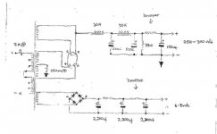
It seems from your description that the B+ has too much ripple; you'll need an additional filter stage. Consider an LC stage, perhaps a 1.5 Hy choke and a 220 uF/400V capacitor( or perhaps 300V and more capacitance if it will remain within its ratings in service ). About $20 will cover it.
You could of course side-step the whole PSRR issue with an active load, aka a CCS...🙂
cheers,
Douglas
The hum is almost definatly due to mains induction if it runs well from your capacitor energy once mains stimulant is removed.
It could also be due to a ground loop, all grounds should be taken to the chosen ground point via a dedicated wire.
Also dont connect chassis (mains earth ground) to signal ground.
These points may help 🙂
It could also be due to a ground loop, all grounds should be taken to the chosen ground point via a dedicated wire.
Also dont connect chassis (mains earth ground) to signal ground.
These points may help 🙂
surfstu said:thanks to coffeedj for sticking with me, in my stupidity i discovered i had taken the output cap from the wrong side of the anode resisor. I have volume again now but major hum issues, the very loud hum/hiss dissapears when the psu is switched off, and i get beutiful clean music for a second or two until the juice runs out.
I am starting to feel like i maybe should have gone down the preamp kit route, but i will prevail!
stuart
Caps on wrong side--it happens. The interesting thing is that you had any output at all--there should be an AC short through the power supply caps at the B+ side. Makes me wonder about the integrity of B+ signal.
HF hiss is not usually ground related. Is it both channels? Could be coming through the heaters, B+ or both.
Is hum 60Hz or 120Hz? If it is 60Hz (low hum), then it is heaters or ground or both. If it 120Hz (higher hum) then it is B+ filter problem. You may have both problems.
Are you using AC or DC heater voltage? If AC--make sure to ground center tap of 6.3V via 100 ohm 2W resistor, otherwise your heaters float with power supply and induce hum. If there is no center tap create a peusdo tap with a 50-100ohm resistor from each leg of LT that connects to a 100ohm resitor to ground. If DC, make sure DC ground is common to system ground.
With a double PI filter using 20H chokes, you should not be having a B+ 120Hz Hum problem. Something else is the problem--could be a bad filter cap (causing both hum and hiss).
Hiss concerns me more than hum. Hum is either ground or filter problem. Hiss means there is noise insertion somewhere in the chain. Are chokes New or Old STock? Do they buzz or hum when you put your ear close--or can you feel a vibration. Bad chokes can cause HF noise that hetrodynes through the system. Is Hiss both channels? If one channel swap tubes. A bad tube will hiss. Is heater voltage correct? High heater voltage can cause a tube to hiss (7V or more).
thanks coffeedj,
i have decided this is not hum, I think a small amount of hum may be present as i get this as the tubes warm up, however this 'noise' drowns out any signs of hum and most of the music too, like i said the only time that this is not present is when i switch off the psu, and i get a few seconds of sweet music.
So i thought there may be a problem with my signal wirring/ stepped attenuator so i disconnected this entirley so that only the grid resistor was hanging from the grid, this resulted in a large hum, getting louder so i had to switch off. I would say this hum was in the region of 120Hz (to my ears)....
could i have damaged the output caps by initially connecting to the B+ side of the anode resistor?
The psu was built for me, cost me a pretty penny and i was assured it would be quiet,
I shall try listening to the chokes themselves for any noise, not quite straightful this linestage for a neewbie!! Am sure if I'd tried another linestage with a different tube it may have been easier, lucky i'm a patient person...
cheers all, without you i wouldn't be in this mess! (joking)
much appreciation to all those who've spent time commenting upon my sinking ship.
stuart
surfstu said:thanks coffeedj,
i have decided this is not hum, I think a small amount of hum may be present as i get this as the tubes warm up, however this 'noise' drowns out any signs of hum and most of the music too, like i said the only time that this is not present is when i switch off the psu, and i get a few seconds of sweet music.
So i thought there may be a problem with my signal wirring/ stepped attenuator so i disconnected this entirley so that only the grid resistor was hanging from the grid, this resulted in a large hum, getting louder so i had to switch off. I would say this hum was in the region of 120Hz (to my ears)....
could i have damaged the output caps by initially connecting to the B+ side of the anode resistor?
The psu was built for me, cost me a pretty penny and i was assured it would be quiet,
I shall try listening to the chokes themselves for any noise, not quite straightful this linestage for a neewbie!! Am sure if I'd tried another linestage with a different tube it may have been easier, lucky i'm a patient person...
cheers all, without you i wouldn't be in this mess! (joking)
much appreciation to all those who've spent time commenting upon my sinking ship.
stuart
A hanging grid will cause hum--this is not an effective debug step. It is not likely the power supply or the caps. The hiss noise is caused by a bad component or tube or PS insertion. If you have any hum at all--this is a problem, but fix the hiss first. THen you can easily debug the hum. This design should be utterly quiet at full volume. Your power supply should be clean--I agree with the builder. Does he have a scope to check B+ and LT noise?
Also, make sure external noise is not causing the problem. Do you have an isolation transformer? If not I'll sell one to anyone for what I paid for them--$15 plus shipping. I have about 1/2 dozen extras. You should always debug through an isolation transformer for saftey reasons--and to clean up house voltage.
Report back on these debug steps.
1. Reconnect grids to attenuator and short grid input to ground. Does hiss remain? If yes continue and leave grids shorted for rest of test.
2. Replace tubes. Does hiss remain? Both Channels? Does swapping change anything? Wiggle in contacts make sure they are tight. If you still have hiss continue.
3. Recheck all wiring connections. Is everything per schematic? Examine solder joints--do you have a cold solder joint? Re-heat to make sure not. Make sure you haven't reversed grid and cathode. Check heater voltage. If OK continue.
4. Lift ground connection to final both 22uf stage PS output cap. THis will increase hum--don't worry about that. Does hiss remain? If yes continue.
5. Reconnect 22uF caps. Disconnect 220uF cap to ground on cathode leg. This will increase hum--don't worry about that. Does hiss remain? If yes continue.
6. Eliminate DC heater temporarily by going directly from AC 6.3V to one tube. Remove the other tube from socket so it won't affect results. Does hiss remain? I suspect at this point that this may be the problem--you have HF noise in your heaters. This is easily fixed with snubbers. If may be that one of the diodes is noisey.
Try these and report back. Also: what kind of resistors did you use when you replaced the 10K with 3.3K?
PS: This is a very simple line stage. You have a problem that should be easy to fix--the point is to debug systematically and eliminate problems.
Progress to kits
Slow, but steady. Biggest job is getting the cases I want to be available. I am slowy working on the Phono-option to the 12B4 kit.
In the meantime, I'm completing the second prototype of my guitar kit. The feedback from local performers is that this design is incredibly flexible, organic, and has phenomenal speed and clarity. I'm very jazzed by the feedback. I want to have at least two kits to offer when I start. One audio, one guitar amp.
-------
I thought I would include a little about my next generation prototype for the guitar amp kit. It relates to SurfStu's problems of noise and hiss---as I had to deal with these problems.
There are four stages of amplification including the power tube, with a total amplification of 1200 leading to the input of the power tube, where the gain is another ~100X or 120,000 total. Of course the final power tube gain is reduced by the transformer ratio of approximately 25--so the final voltage gain is actually only 4,800.
Compare this to the 12B4 amp where total voltage gain is 5, and you would think that I would have HUGE, HUGE problems with hum and hiss. In point of fact, by using proper layout and proper design, I do not even need to use a separate power supply. I don't need DC heater voltage except for the very first stage--if I want absolutely no hum at all. I used a very simple bridge circuit to give DC heaters to the first stage input, and with that the hum is absolutely zero at full gain through entire system. This even includes a front panel pot to change screen grid voltage on output tube. How is this accomplished?
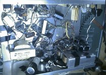
Mainly by following the layout rules I stated earlier. The power supply is on the same chassis, but shielded by proper space use. I am also using 6CG7 tubes for first three stages, which allows grounding of the heater plane on pin 9. The 12AU7, which is equivalent electronically, does not have this feature and is noisier.
Look at the picture and notice that all leads are twisted, B+ power runs at right angles to heater wires, and chokes are hidden behind a bracket to shield them. AC power and rectification is all on one side, small signals are on opposite corner. Transformer and choke elements are at right angles or 45 degrees with respect to each other. Wires are dressed along the bottom or sides, and no small signal leads pass near AC carrying wires. A star ground is used on the power choke shield plane, and all ground wires act as shields by running next to B+ wires. Cathode elements are physically on top of B+ and grid elements for each tube and act as a ground plane shield to those elements. B+ elements are separated by simple cascading RC filters to create a continously cleaner supply as the signal input voltage decreases.
The point is that extreme measures are not required to get very quiet circuits. DC heaters should be used only when absolutely necessary--there is a tendency nowdays to use them 'just in case. Here there is a gain of almost 5000 with no hum, and only one DC heater element. Even that was not absolutely necessary--I just wanted to see what was required to take hum to zero.
There is one final thing I'm trying to do--that is reduce the quiet gentle hiss at full gain to zero. I'm picking up the thermionic noise in the first stage tubes. Because of the gain of the system, this may not be an issue. THe master gain has to be turned down to the point where the hiss is not audible when the guitar is at normal volume. Thus, my system gain is too large, but I'm leaving it in for guitarists who may want to play with distortion. I'm going to try a few tricks, but even if they don't work--the amp is studio ready according to my testers.
This is why I love point-to-point wiring and tube design. You can do amazing things by taking advantage of very simple design rules.
Hope this was helpful. I wish I had known this when I started, becuase I spent a lot of time running down problems that were simple the result of bad layout and in-attention to fundamental details.
TubeMack said:Coffedj
Any updates on progress?
Slow, but steady. Biggest job is getting the cases I want to be available. I am slowy working on the Phono-option to the 12B4 kit.
In the meantime, I'm completing the second prototype of my guitar kit. The feedback from local performers is that this design is incredibly flexible, organic, and has phenomenal speed and clarity. I'm very jazzed by the feedback. I want to have at least two kits to offer when I start. One audio, one guitar amp.
-------
I thought I would include a little about my next generation prototype for the guitar amp kit. It relates to SurfStu's problems of noise and hiss---as I had to deal with these problems.
There are four stages of amplification including the power tube, with a total amplification of 1200 leading to the input of the power tube, where the gain is another ~100X or 120,000 total. Of course the final power tube gain is reduced by the transformer ratio of approximately 25--so the final voltage gain is actually only 4,800.
Compare this to the 12B4 amp where total voltage gain is 5, and you would think that I would have HUGE, HUGE problems with hum and hiss. In point of fact, by using proper layout and proper design, I do not even need to use a separate power supply. I don't need DC heater voltage except for the very first stage--if I want absolutely no hum at all. I used a very simple bridge circuit to give DC heaters to the first stage input, and with that the hum is absolutely zero at full gain through entire system. This even includes a front panel pot to change screen grid voltage on output tube. How is this accomplished?
Mainly by following the layout rules I stated earlier. The power supply is on the same chassis, but shielded by proper space use. I am also using 6CG7 tubes for first three stages, which allows grounding of the heater plane on pin 9. The 12AU7, which is equivalent electronically, does not have this feature and is noisier.
Look at the picture and notice that all leads are twisted, B+ power runs at right angles to heater wires, and chokes are hidden behind a bracket to shield them. AC power and rectification is all on one side, small signals are on opposite corner. Transformer and choke elements are at right angles or 45 degrees with respect to each other. Wires are dressed along the bottom or sides, and no small signal leads pass near AC carrying wires. A star ground is used on the power choke shield plane, and all ground wires act as shields by running next to B+ wires. Cathode elements are physically on top of B+ and grid elements for each tube and act as a ground plane shield to those elements. B+ elements are separated by simple cascading RC filters to create a continously cleaner supply as the signal input voltage decreases.
The point is that extreme measures are not required to get very quiet circuits. DC heaters should be used only when absolutely necessary--there is a tendency nowdays to use them 'just in case. Here there is a gain of almost 5000 with no hum, and only one DC heater element. Even that was not absolutely necessary--I just wanted to see what was required to take hum to zero.
There is one final thing I'm trying to do--that is reduce the quiet gentle hiss at full gain to zero. I'm picking up the thermionic noise in the first stage tubes. Because of the gain of the system, this may not be an issue. THe master gain has to be turned down to the point where the hiss is not audible when the guitar is at normal volume. Thus, my system gain is too large, but I'm leaving it in for guitarists who may want to play with distortion. I'm going to try a few tricks, but even if they don't work--the amp is studio ready according to my testers.
This is why I love point-to-point wiring and tube design. You can do amazing things by taking advantage of very simple design rules.
Hope this was helpful. I wish I had known this when I started, becuase I spent a lot of time running down problems that were simple the result of bad layout and in-attention to fundamental details.
A success...
finally got rid of the noise that was like tuning between fm stations.
1. Shorted grid input to ground - no change.
2. Couldn't roll tubes as i have only two, although noise was present in both channels.
3. Rechecked wiring
4.lifted ground connection to 22uf ps caps, no change, and no increased hum either.
5. disconnected 220uf caps from cathode, no change
6. Heater directly to AC, NOISE GONE!! but new hum present.
I accidently forgot to reconect cathode caps when i tested ac heater.
I also forgot that i had shorted the heater pins 4 and 5 to ground when i tested ac heaters.
so i disconnected the ac heater from ground and reconnected the cathode caps and now the hum is huge, bigger than ever. However I am still very pleased that i have lost that HF noise, I feel like i am making progress and would like to thank coffeedj for his time and patience.
Does the ac heater need to be shorted to ground?
how do i make a snubber? and is it likley that one of the diodes for dc rectification is faulty?
P.s. I replced the 22uf ps caps with 47uf as said by coffeedj, i have also purchased a 3k3 resistor for the anode, 100uf for the cathode and 1uf bypass audio capacitor for the cathode.
the anode resistor is chunky green high wattage, but i also got some new cathode resistors but these are .25 watt. Can i Use these on the cathode? I have not changed anything apart from the 22uf to 47uf ps caps. But i bought these components as per coffeedj recommendation because the sound is a little mushy (if i ignore the hum) and i hoped these new component values will help me get nearer to my desired sound.
It is very bassy at the moe but i thought buying larger output caps will only increase the bass? I am about to go from .33uf to 2.2uf.
Anyway, i look forward to tweaking the sound once i have quiet heaters!
cheers stuart
Attachments
p.p.s
i also purchase a 10000uf cap, 35V 'HI-RIPPLE' that i was going to use for the dc heaters, not quite sure how i was going to do that... +heater to ground via cap?
anyway, I am sure that this is an afterthought to geting the initial heater supply correct...
sorry to be such a newbie with lots of questions
stuart
HF Noise gone
Well it feels good to know than my suspiscion was correct, but it was good to rule out everything else. You learned along the way that the B+ is probably plenty clean as is. Changing to 47uF will help reserve, but not change the hum perceptibly. Should tighten up bass a little.
The AC heater needs to be 'referenced' to ground, not necessarily shorted. The hum you are now hearing is most likely the floating heaters. You should be able to get zero hum on the 12B4 with AC heaters--and bypass the whole DC problem completely. THis is a better solution as with DC heaters there is ion drift that occurs in the heater element. You should have a reverse polarity switch for DC heaters and switch every couple of months or so.
However, no need to go down that path. Reference your heaters to ground back at the PSU ground as follows (this assumes there is no center tap for your 6.3V supply): Connect one end of two 50 ohm 1/2W or 1 W resistor to each leg of the AC Heater. Connect the other ends of the 50 ohm resistors together and to one end of a 100 ohm resistor. Connect the other end of the 100 ohm resistor to PSU ground. This will 'reference' the AC heaters to ground through a common center voltage point and keep them from floating and inducing hum in the 12B4. If you have a 6.3V center-tap connect that directly through a 100 resistor to ground. After doing this your hum should be zero. If you have any residual hum, then check out the layout of your AC heater leads. From your description above, it sounds as though your heater runs need to be optimized. Run them as indicated in my previous posts and hum should completely disappear.
Your DC rectification is faulty at some point--debugging requires checking the diodes and checking the caps and maybe adding snubbers. Adding a large cap won't fix anything.
Larger output caps will improve bass response, but does not affect 'mushiness', rather it will improve. You may be hearing a roll-off.
1/4 watt cathode resistors won't work. 21 ma through 470 ohms is .2W. P = I^2*R. Cathode resistor should be 3X Power minimum to keep from drifting : Thus 1 W is minimum for this design.
surfstu said:A success...
finally got rid of the noise that was like tuning between fm stations.
1. Shorted grid input to ground - no change.
2. Couldn't roll tubes as i have only two, although noise was present in both channels.
3. Rechecked wiring
4.lifted ground connection to 22uf ps caps, no change, and no increased hum either.
5. disconnected 220uf caps from cathode, no change
6. Heater directly to AC, NOISE GONE!! but new hum present.
I accidently forgot to reconect cathode caps when i tested ac heater.
I also forgot that i had shorted the heater pins 4 and 5 to ground when i tested ac heaters.
so i disconnected the ac heater from ground and reconnected the cathode caps and now the hum is huge, bigger than ever. However I am still very pleased that i have lost that HF noise, I feel like i am making progress and would like to thank coffeedj for his time and patience.
Does the ac heater need to be shorted to ground?
how do i make a snubber? and is it likley that one of the diodes for dc rectification is faulty?
P.s. I replced the 22uf ps caps with 47uf as said by coffeedj, i have also purchased a 3k3 resistor for the anode, 100uf for the cathode and 1uf bypass audio capacitor for the cathode.
the anode resistor is chunky green high wattage, but i also got some new cathode resistors but these are .25 watt. Can i Use these on the cathode? I have not changed anything apart from the 22uf to 47uf ps caps. But i bought these components as per coffeedj recommendation because the sound is a little mushy (if i ignore the hum) and i hoped these new component values will help me get nearer to my desired sound.
It is very bassy at the moe but i thought buying larger output caps will only increase the bass? I am about to go from .33uf to 2.2uf.
Anyway, i look forward to tweaking the sound once i have quiet heaters!
cheers stuart
Well it feels good to know than my suspiscion was correct, but it was good to rule out everything else. You learned along the way that the B+ is probably plenty clean as is. Changing to 47uF will help reserve, but not change the hum perceptibly. Should tighten up bass a little.
The AC heater needs to be 'referenced' to ground, not necessarily shorted. The hum you are now hearing is most likely the floating heaters. You should be able to get zero hum on the 12B4 with AC heaters--and bypass the whole DC problem completely. THis is a better solution as with DC heaters there is ion drift that occurs in the heater element. You should have a reverse polarity switch for DC heaters and switch every couple of months or so.
However, no need to go down that path. Reference your heaters to ground back at the PSU ground as follows (this assumes there is no center tap for your 6.3V supply): Connect one end of two 50 ohm 1/2W or 1 W resistor to each leg of the AC Heater. Connect the other ends of the 50 ohm resistors together and to one end of a 100 ohm resistor. Connect the other end of the 100 ohm resistor to PSU ground. This will 'reference' the AC heaters to ground through a common center voltage point and keep them from floating and inducing hum in the 12B4. If you have a 6.3V center-tap connect that directly through a 100 resistor to ground. After doing this your hum should be zero. If you have any residual hum, then check out the layout of your AC heater leads. From your description above, it sounds as though your heater runs need to be optimized. Run them as indicated in my previous posts and hum should completely disappear.
Your DC rectification is faulty at some point--debugging requires checking the diodes and checking the caps and maybe adding snubbers. Adding a large cap won't fix anything.
Larger output caps will improve bass response, but does not affect 'mushiness', rather it will improve. You may be hearing a roll-off.
1/4 watt cathode resistors won't work. 21 ma through 470 ohms is .2W. P = I^2*R. Cathode resistor should be 3X Power minimum to keep from drifting : Thus 1 W is minimum for this design.
thanks again coffeedj, let me know if you want some help with your website, i feel like i owe you a favor or two! I noticed quite a few of your links broken and and your linestage design seems to have completley dissapeared. However you may enjoy the diy aspect of html coding.
so, i spent hours trying to fing the CT for the filament heaters, I know its there but i didn't get to it. So i only had a 2watt 100R resistor and i referenced one leg of the ac heater supply to ground. It worked, very minimal hum and i will purchase the 4 neccessary 50R resistors to referece both legs to ground.
OK, so what is roll off? my experience with studio work tells me that it is some kind of curve rolling off the top end/ higher frequencies. I think this could be what i called mushiness, especially seeing as i still have .33uf output cap.
how do i fix roll off? I still have the compnonents you recommended for cathode and anode etc. would this help?
cheers again
stuart
- Status
- Not open for further replies.
- Home
- Amplifiers
- Tubes / Valves
- 12B4 Line Stage Amp