Size of chokes
Sorry, I read power chokes. The previous footprint is correct for both power chokes and plate chokes, but the height of plate chokes is 32, not 35 mm.
TubeMack said:Can I get the dimensions of those Plate chokes? I'm sizing the chassis for the build.
Sorry, I read power chokes. The previous footprint is correct for both power chokes and plate chokes, but the height of plate chokes is 32, not 35 mm.
Hmmm, I still seem to still be missing a dimension. If its bolted down to the plate, how high does it stick up?
dimensions
The dimensions in the PDF are the footprint. Height is 32mm for plate choke and 35 mm for filter choke. You will want to mount the plate choke inside the case, not on top. Both are open chokes, and susesptible to EMI, but only the plate choke really matters.
TubeMack said:Hmmm, I still seem to still be missing a dimension. If its bolted down to the plate, how high does it stick up?
The dimensions in the PDF are the footprint. Height is 32mm for plate choke and 35 mm for filter choke. You will want to mount the plate choke inside the case, not on top. Both are open chokes, and susesptible to EMI, but only the plate choke really matters.
i have built my power supply and am now embarking upon the 12b4 linestage, my question is:
if i have dc HT and LT coming from powersupply to 12b4 (another unit) via an umbilical cord, should i just braid all four wires together, i.e. twist them all together?
stuart
if i have dc HT and LT coming from powersupply to 12b4 (another unit) via an umbilical cord, should i just braid all four wires together, i.e. twist them all together?
stuart
surfstu said:i have built my power supply and am now embarking upon the 12b4 linestage, my question is:
if i have dc HT and LT coming from powersupply to 12b4 (another unit) via an umbilical cord, should i just braid all four wires together, i.e. twist them all together?
stuart
Twist the LT wires together, and the HT wires together. DO NOT braid all four together. That will insert noise from the LT supply into the B+ Voltage. Twisting then individually will provide separate Common Mode rejection. If your LT is not DC, consider putting a shield around the HT twisted pair in the form of a single small guage bare wire tightly wrapped, but loosely spaced along the twisted HT pair which grounds at the power supply end only.
Finally, when you make an external run from a power supply it is a very good idea to have your final stage of filtering on the pre-amp side. If your 0D3's are on the 12B4 chassis, this will do the trick. If not--you need to add a final RC stage in the form of a small resistor (100-220 ohms) with a 47uF EL cap bypassed by a .47uF OIP or good quality Poly Cap. The HT leg picks up some hum and noise in the run, and that needs to be filtered to ground to keep from corrupting your B+. It will be very small, but it is there. The 100-220 ohm resistor protects the the OD3 from oscillations, and the 47uF to ground shorts any AC hum induced in the line run. The .47 bypass handles high frequency induced noise and stabilzes the EL performance. Do not add this mod if your 0D3's are on the pre-amp chassis--it adds nothing to the performance.
Similarly, if you are using DC LT, add a 12,000uF (approximately) to ground at the pre-amp side. No-ByPass or dropping resistor is required. You just want to trap any induced hum--and with the high current for filament there will be a little.
Last point is just a check. Long runs of LT require heavy wire. 18 guage is a minimum, 16 guage is better. HT is much more forgiving--I typically use 20 guage, or 18 if it is over 24 inches.
Thanks very much for your time coffeedj, very helpful, I am not actually building your linestage but a much simpler one based on franks design.... but i have been following this thread avidly and i am sure to want to progress soon, in which case i may well be building one of your designs.
Do i need to ground the center pin of the valve socket? I think I do, and how important is it to get a star shaped ground inside the chassis, i'm trying to do get the star shape but not sure i can pull it off!!
stuart
Do i need to ground the center pin of the valve socket? I think I do, and how important is it to get a star shaped ground inside the chassis, i'm trying to do get the star shape but not sure i can pull it off!!
stuart
Attachments

oh, and is there any way to theoretically calculate the input resistance/impedance of the linestage i just posted?
how is this done? other than just measuring the resistance across signal and ground of the input after it is built?
cheers stuart
how is this done? other than just measuring the resistance across signal and ground of the input after it is built?
cheers stuart
surfstu said:Thanks very much for your time coffeedj, very helpful, I am not actually building your linestage but a much simpler one based on franks design.... but i have been following this thread avidly and i am sure to want to progress soon, in which case i may well be building one of your designs.
Do i need to ground the center pin of the valve socket? I think I do, and how important is it to get a star shaped ground inside the chassis, i'm trying to do get the star shape but not sure i can pull it off!!
stuart
Star Ground just means a single ground point for all grounds--it doesn't refer to the shape, so you will be able to do it.
Tech Tips:
1. Run your grounds next to the chassis floor and bring them to the center to run to the star connection--best located in the rear close to the transformer. Star connection is made at the center tap of the transformer in a full wave rectifier configuration.
2. Run all your heater wires down one side nestled in the corner of a chassis. Bring them out at 90 degrees to the tubes, and place them on the chassis floor. WIre LT first so that heater wires are closest to chassis floor. When crossing LT wires, do so at right angles. TIGHTLY twist LT pairs.
3. Run your HT wires on the oppisite side from LT wires, or down center next to ground wires.
4. Do not run grid connections across or close to LT wires. Come from the oppisite side of valve or separate in space by a couple of inches. Not as important with DC LT, but still good practice.
5. Always dress wires neatly with common feeds running in same planes.
6. Always protect grid connections. I use tightly twisted pair rather than shielded wire--it has lower capacitance and superior CMR properties. Ground only ONE side of the twisted pair--doesn't matter where since all grounds terminate at the star. I use Cat 5 or Cat 6 10Base-T wire for my low signal paths and grid connections. It is very cheap, is extremely high quality, and comes in twisted pairs after you strip it out of the case. Buy a 50 foot roll and you will have a lifetime supply of ultra-high quality low signal wire. To make a uniform tightly twisted pair, get a 2' length of a wire pair, connect one end to a vise and the other to your drill. grip the wire loosley at the vice end and start the drill. Use your hand to dress and follow the twist from the vice back to the drill head. With a little practice you can create perfect twisted pairs in seconds. BTW: Some audiophiles use this for speaker connection wire as well--paralleling multiple strands.
7. I also use twisted pair for output connections--this is not commonly done as the CMR is high for low impedance runs, but it does improve the channel separation and allows you to tightly run output wires in a bundle.
Grounding the center pin is mainly for high frequency designs--not really necessary for audio work. However, if you are using a tube that has a shield, like a 6CG7, it is always a good idea to ground the shield--pin 9 in this case. Note that this ground does not need to connect to the star--just ground to the chassis at the socket.
Input Impedance and design.
Yes. Morgan's books give the tech background, and there is a shareware .xls that does it for common designs--don't remember where I saw it, but someone on the thread might. You can measure resistance across the input, but that is DC resistance and you want AC impedance. To measure AC impedance manually use a signal generator with a low output impedance feeding through a 10K series resistor. Add a shunt resistor in parallel with the input to your 12B4 grid. With tubes and heated and warm measure the AC signal at the shunt point. When the Signal with the shunt is equal to 1/2 the signal without the shunt--your AC input impedance is equal to the shunt resistance. Use 1KHz to make sure you are not getting roll-off from capacitance.
I used to calculate by hand--but now I cheat and use the Glassware program.
If this is a 12B4 your AC input resistance is about 250K.
Comment 1: If this is a 12B4, your output cap is too small. Assuming a 10K input impedance at the next stage (standard for pro audio equipment), your 3db point is at 44Hz. Change to a 3.3uF and it drops to 4.4Hz--fine for tube amps. At a 50K input to the next stage, your 3db point is less than 1 Hz. To use this .33uF cap, you next stage needs to have >200K input impedance.
Comment 2: I assume you have a B+ in the 300V range to be able to use the 10K anode reisistor. Rule of thumb is ~3X for anode resistance to plate resistance--putting your anode resistor at 3K, and lowering B+. At 300V B+ you are running 20ma (good), but Va is ~95V. This is a little low for the 12B4--120V is about right for best sound. If you change Ra to 3K, it does reduce gain slightly, but also significantly lowers output impedance--a very good idea if you are not adding a cathode follower stage. Also improves distortion, but does reduce PSSR. You would need to beef up power supply capacitance if you follow these rules. Changing 22uF to 47uF in the RC filters should do the job.
Comment 3: Your bypass capacitor is oversized and doesn't really add anything. Reduce to 100uF and bypass the bypass with a 1uF non-polar for best results.
Summary of my recommended changes for this design:
Ra = 3.3K
B+ = 200
Rk = 680
Cout = 3.3uF
Cbypass = 50-60uF
Rload=100K
Cfilter=47uF or more
surfstu said:oh, and is there any way to theoretically calculate the input resistance/impedance of the linestage i just posted?
how is this done? other than just measuring the resistance across signal and ground of the input after it is built?
cheers stuart
Yes. Morgan's books give the tech background, and there is a shareware .xls that does it for common designs--don't remember where I saw it, but someone on the thread might. You can measure resistance across the input, but that is DC resistance and you want AC impedance. To measure AC impedance manually use a signal generator with a low output impedance feeding through a 10K series resistor. Add a shunt resistor in parallel with the input to your 12B4 grid. With tubes and heated and warm measure the AC signal at the shunt point. When the Signal with the shunt is equal to 1/2 the signal without the shunt--your AC input impedance is equal to the shunt resistance. Use 1KHz to make sure you are not getting roll-off from capacitance.
I used to calculate by hand--but now I cheat and use the Glassware program.
If this is a 12B4 your AC input resistance is about 250K.
Comment 1: If this is a 12B4, your output cap is too small. Assuming a 10K input impedance at the next stage (standard for pro audio equipment), your 3db point is at 44Hz. Change to a 3.3uF and it drops to 4.4Hz--fine for tube amps. At a 50K input to the next stage, your 3db point is less than 1 Hz. To use this .33uF cap, you next stage needs to have >200K input impedance.
Comment 2: I assume you have a B+ in the 300V range to be able to use the 10K anode reisistor. Rule of thumb is ~3X for anode resistance to plate resistance--putting your anode resistor at 3K, and lowering B+. At 300V B+ you are running 20ma (good), but Va is ~95V. This is a little low for the 12B4--120V is about right for best sound. If you change Ra to 3K, it does reduce gain slightly, but also significantly lowers output impedance--a very good idea if you are not adding a cathode follower stage. Also improves distortion, but does reduce PSSR. You would need to beef up power supply capacitance if you follow these rules. Changing 22uF to 47uF in the RC filters should do the job.
Comment 3: Your bypass capacitor is oversized and doesn't really add anything. Reduce to 100uF and bypass the bypass with a 1uF non-polar for best results.
Summary of my recommended changes for this design:
Ra = 3.3K
B+ = 200
Rk = 680
Cout = 3.3uF
Cbypass = 50-60uF
Rload=100K
Cfilter=47uF or more
thanks coffedj
these are the only parts i have, but i will store your post so i know where to look when trouble shooting, am hoping to test tonight.....
there seems to be 3 heater pins on the 12b4... pins 3,4 and 5? my heater supply is dc but i'm sure which pins to use, also there are 2 grid pins,2 and 7, do these need to be joined?
cheers stuart
p.s. the power amp is leak stereo 20, and i've just noticed the guy has given me audio note caps for the output and these are .33mf not .33uf so i guess i'm ok here?
hey-Hey!!!,
Pins 4&5 are for 12.6V, tie 4&5 together and apply 6.3 to pin 3 and the 4&5 pair.
cheers,
Douglas
Pins 4&5 are for 12.6V, tie 4&5 together and apply 6.3 to pin 3 and the 4&5 pair.
cheers,
Douglas
surfstu said:thanks coffedj
these are the only parts i have, but i will store your post so i know where to look when trouble shooting, am hoping to test tonight.....
there seems to be 3 heater pins on the 12b4... pins 3,4 and 5? my heater supply is dc but i'm sure which pins to use, also there are 2 grid pins,2 and 7, do these need to be joined?
cheers stuart
p.s. the power amp is leak stereo 20, and i've just noticed the guy has given me audio note caps for the output and these are .33mf not .33uf so i guess i'm ok here?
Unless the caps are the size of a transformer, the 'm' means micro, not milli. These are not EL (electrolytic) caps are they? Those can be small at high voltages but the sound will suck badly. You want to use non-polar caps for the output. EL caps have a shielded (metal end) and a polarity mark--either a plus, or minus, or black bar.
I guess you were right coffeedj, I can't test because like I said, I only have the parts for the schematic I posted.
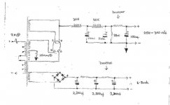
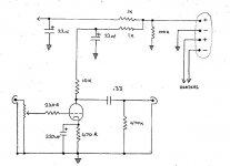
I finally finished my first project, the 12b4 linestage, I fired it up and no fireworks!! However the output is far too low, it is barley audible, I'm not sure how to proceed, I don't really want to make all the changes you suggested at once. Any suggestions on what I could try first to get some volume? Which voltages i should maybe be checking? etc?
I have posted the schematic for the psu and linestage again, any help would be much appreciated.
thanks in advance,
stuart
Attachments
"was i meant to short pins 2 and 7 for the grid on the 12b4? i just used pin 2?"
I don't think thats the problem.
I don't think thats the problem.
surfstu said:I guess you were right coffeedj, I can't test because like I said, I only have the parts for the schematic I posted.
I finally finished my first project, the 12b4 linestage, I fired it up and no fireworks!! However the output is far too low, it is barley audible, I'm not sure how to proceed, I don't really want to make all the changes you suggested at once. Any suggestions on what I could try first to get some volume? Which voltages i should maybe be checking? etc?
I have posted the schematic for the psu and linestage again, any help would be much appreciated.
thanks in advance,
stuart
Power Supply looks fine, although the voltage may be a little low. Check the voltage at pin 9--should be over 90VDC.
Also--are you getting heater glow in the 12B4? Pin 3 goes to LT Plus, pins 4&5 go to ground (or LT minus--which should be tied to ground directly or through a 100 ohm resistor). Should be a warm red--check voltage between pins 3 and 5--if it is less than 5.0VDC, then that is your problem.
Report back on these and if this doesn't fix it we can look at next most likely candidate.
TubeMack said:"was i meant to short pins 2 and 7 for the grid on the 12b4? i just used pin 2?"
I don't think thats the problem.
Pin 2 is just fine. Pin 7 can remain unconnected, but check for cold solder joints. The fact that you are getting a little sound suggests low B+ or low LT.
- Status
- Not open for further replies.
- Home
- Amplifiers
- Tubes / Valves
- 12B4 Line Stage Amp