The ECC88 has high gm and fairly high mu too, and sees about eight times more grid current as a consequence.
The datasheets disagree with you. 😀
ECC83 are some of the worst grid current distortion tubes I've ever tested unless they're biased higher than 1V or so.
Which data sheets exactly?The datasheets disagree with you. 😀
ECC83 are some of the worst grid current distortion tubes I've ever tested unless they're biased higher than 1V or so.
Yes, grid current is always present for bias less than -0.5V. Even the ECC83 needs a bias greater than -1V to be in the 'safe zone' when allowing for manufacturing spread. Nevertheless, I suggest your repeat your tests!
EDIT: Bare in mind that I'm talking about the ECC88. The E88CC *may* have some clever differences to reduce grid current, I don't know.
Right, confession time: I think I confused myself. I should have said that higher mu also leads to higher grid current, other things being equal. Basically low grid-cathode spacing leads to higher grid electron current. Low grid-cathode spacing contributes to both high mu and high gm, although both depend on others things too. To a first approximation, mu depends on the ratio of anode-cathode spacing to grid-cathode spacing. For a given ratio, you can adjust gm and anode current by changing the size and shape of the whole thing.
I understand that very high gain valves have the grid virtually touching the space charge so it is easy for the grid to pick up electrons.
Some people use the ECC88 for almost everything, including phono inputs. Some say it is very low noise, others find that even ECC83 can beat it. Grid current may be an issue, which people often forget about. It can be a problem with the ECC83 too, as there is a very narrow bias range between cutoff/distortion and grid current. I found this when using it as a LTP phase splitter in a modified 5-10. If the anode voltage gets too low then grid current introduces imbalance. Almost any valve can have grid current unless biassed at least to -1V, some require -1.5V.
Last edited:
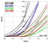
Nice graph, and I am surprised that the knee for 82 and 83 is as high as 0V, but it would be nice to see the region for Vgk -0.5 to -1.5V. Also, Vak at 12V might not be high enough to create many positive ions so you are only seeing electronic grid current.
I have done the same tests at higher voltages some years ago, and the overall pattern is the same, only the magnitude of the grid current is reduced (and not by much in this region), suggesting to me that ionization is a non-issue in the negative grid region (I think I have some papers which discussed ionization current in some of the ECCx family, and it was pretty darn small!)Also, Vak at 12V might not be high enough to create many positive ions so you are only seeing electronic grid current.
Last edited:
Very interesting graphs MerlinB,
Of course the area left of far left and a blown up scale on the vertical to 10uA FS, would be of even more interesting, but this graphs shows the difference in quality and construction of tubes with the same type-numbers.
This can be one of the clues how the same type number tube of different brands/years sounds so different.
According to the National Semiconductor papers, the combined LRC generator impedance from a typical MM Phono cartridge, ADC27, is 43,6 KOhm at 9600Hz.
We must remember that it takes only 21uA in 47KOhm to create one volt, and 1uA through 47KOhm makes a voltage of 47mV.
So I still recommend the 600 Ohm versus 47 KOhm generator impedance test @ 1KHz, to discover if there is an increase in distortion caused by an non linear function in the grid current.
No, ionisation becomes important in the negative grid region as it is the dominant source of grid current below about -1.5V where the electron current stops. You said that the grid current reduces for higher Vak. This is exactly what I would expect, as the ionic current is the opposite polarity. Even higher anode voltages will change the sign of the net grid current. It is the region around -1.5V and lower which is interesting, as this is where valves are usually biased. The grid current might only be 0.5uA but it can be very non-linear and so introduce distortion from a high impedance source. It is also a source of noise.
Fair enough, I'll have to look into it! Naturally, it is not easy to measure such small currents.No, ionisation becomes important in the negative grid region as it is the dominant source of grid current below about -1.5V where the electron current stops.
It is a source of noise, but it is sufficiently small with respect to cathode-current noise as to be entirely irrelevant at audio frequencies.The grid current might only be 0.5uA but it can be very non-linear and so introduce distortion from a high impedance source. It is also a source of noise.
Interestingly, under certain situations an impedance in series with the grid (current) can predistort the signal in such a way as to cancel some of the distortion generated in the valve itself!🙄
On another note, after inspecting the Req = 2.5/gm formula for noise, it appears to assume that the anode current is about 8.6 times the magnitude of gm (e.g, a 5mA/V triode running at 43mA). In this sense it is entirely unrealistic for preamp valves, and will overestimate Req by as much as a factor of ten at 'normal' current levels. Using a more realistic anode current of 2 times gm modifies the formula to: Req = 0.6/gm
However, I have yet to obtain the very original 1941 paper where the 2.5/gm figure originates.
Last edited:
If 0.6/gm was happening then an ECC88 would be same en as a 2SK170 for around 50R. Rather far stretched.
This is why I need to get hold of the original paper, to see how they figured the space-charge reduction factor.If 0.6/gm was happening then an ECC88 would be same en as a 2SK170 for around 50R. Rather far stretched.
(The X/gm figure is only for shot noise, incidentally. Flicker noise would also need to be taken into account)
Last edited:
Which data sheets exactly?
http://tubedata.milbert.com/sheets/009/e/E83CC.pdf
http://tubedata.milbert.com/sheets/009/e/E88CC.pdf
These are both SQ versions, so if there are any tricks to lower ig, presumably it's been done for both.
Hello,
In WWII my father was U.S. Army Signal Corps and repaired radios and cameras in France. Much of my electronics knowledge came from the training manuals that he brought home and I found in his closet. I have just been reading Section 13.4 in Vol. 18 of the MIT Radiation series.
The high gm low noise tubes we are speaking of here are born of radio frequency technology. Much of the noise discussed in the old musty pages is well beyond the audible frequencies. One thing that is prominent is that there can be considerable differences between theory and practice concerning R = 2.5/gm, but there is a general trend (as in do not get locked into the math and theory). Another thing I found interesting was the discussion of low bias voltage, low plate voltage & high gm leading to grid current and resulting in grossly increased grid noise. The offered solution was to experimentally increase the plate voltage and grid bias. The increase in plate voltage and grid bias maintains high gm and reduces grid current / noise.
Much of this has been discussed here by SY and others. There is nothing new, rediscovering is fun.
DT
All just for fun!
You will see this in older books and articles. I strongly suspect that it is based on ignorance of the effect of higher-order distortion, which was not fully recognised at the time. It is true that grid current distortion can add some second-order to cancel some of the inherent second-order; the graphs in these books/articles show that. Some of them also show a rise in third-order at around the same point. What they don't show is a rise in even higher orders too. The result is likely to be lower THD and horrible sound!Interestingly, under certain situations an impedance in series with the grid (current) can predistort the signal in such a way as to cancel some of the distortion generated in the valve itself!
With regard to the 2.5 numerator in the noise equivalent formula, it does come from some assumption about the relationship between anode current and gm. It may be that modern higher gain valves do not fit the assumption too well. However, I don't think it can change too much as we still have a hot cathode producing a hot space charge. To get the number down to 1 you would need to show how the effective temperature of the space charge can be equal to room temperature.
The effect of grid current noise depends on the source impedance. 1uA of current gives shot noise of 5.7 x 10^(-13) A/root Hz, so a 50K source impedance would turn it into 28nV/root Hz. This is big enough to be significant.
OK, assume 10nA. Then noise voltage is 2.8nV/root Hz. Small but not entirely negligible. I was just trying to see what order of magnitude we were dealing with.
OK, assume 10nA. Then noise voltage is 2.8nV/root Hz. Small but not entirely negligible. I was just trying to see what order of magnitude we were dealing with.
Hello,
At what grid bias is this happening?
Dt
Somewhere negative of -1V? It all depends on the valve. I was trying to show that a plausible grid current can generate non-negligible noise in a highish source impedance such as a MM cartridge. It could be worse than I stated, as the net grid current will be the difference between electronic and ionic current. These two currents are independent of each other and of opposite sign, so they should be dealt with separately and then added in quadrature. Putting it another way, if there is 15nA of one and 25nA of the other so a net current of 10nA then noise should be calculated from 40nA - twice as much noise.
As it is essentially shot noise I would expect it to be white. However, there always seems to be a bit of flicker noise lurking somewhere so I would not rule out a rise at LF. The grid noise also rises at VHF but few people have audio amps going up to 50MHz! (Maybe I could start a new fashion for very wideband amps, and create jobs for those of us who can build RF gear?)
- Status
- Not open for further replies.
- Home
- Amplifiers
- Tubes / Valves
- 12AU7 Phono Stage