You mean this book?
Electronics-Experimental Techniques : William C. Elmore & Matthew Sands : Free Download & Streaming : Internet Archive
(still looking for the derivation)
No, they did a book called just "Electronics." Part of the MIT Radiation series.
Hello,
Rnc = 2.5/gm is derived on page 625 as formula 17 in Chapter 13 of Vacuum Tube Amplifiers volume 18 of the MIT Radiation series. In the footnotes credit is given to W. A. Harrris, RCA April 1941.
This could also show up in another of the MIT Radiation series.
DT
Rnc = 2.5/gm is derived on page 625 as formula 17 in Chapter 13 of Vacuum Tube Amplifiers volume 18 of the MIT Radiation series. In the footnotes credit is given to W. A. Harrris, RCA April 1941.
This could also show up in another of the MIT Radiation series.
DT
OK, we can agree, that the 12AU7 is not suitable for the input stage in a RIAA preamp.
Thanks Sy for your excellent analyzis of this &the RIAA network noise chart!!
But i've had some trouble with the medium u & high transconductance tubes (E88CC-family), that are prone to distort in the treble due to "excessive dynamic" (my expression) grid currents these tubes suffers from. This phenomena also accentuates cracks and pops in the record, as the transients are rectified and integrated in the grid-cathode circuit.
Specially as the generator impedance & output level from a MM PU gets quite high in the treble area. Maybe this creates the IMO more harsh sound of these tubes.
So, for input tube, I still prefer the high u & low transconductance tubes (5751/12AX7) at low Ia, as the are not affected to the above and the little higher tube noise contribution is of marginal significance compared to the Johnson noise from the PU itself.
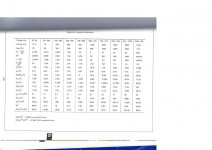
See charts below scanned from: National Semiconductor Audio/Radio Handbook 1980:
Thanks Sy for your excellent analyzis of this &the RIAA network noise chart!!
But i've had some trouble with the medium u & high transconductance tubes (E88CC-family), that are prone to distort in the treble due to "excessive dynamic" (my expression) grid currents these tubes suffers from. This phenomena also accentuates cracks and pops in the record, as the transients are rectified and integrated in the grid-cathode circuit.
Specially as the generator impedance & output level from a MM PU gets quite high in the treble area. Maybe this creates the IMO more harsh sound of these tubes.
So, for input tube, I still prefer the high u & low transconductance tubes (5751/12AX7) at low Ia, as the are not affected to the above and the little higher tube noise contribution is of marginal significance compared to the Johnson noise from the PU itself.
See charts below scanned from: National Semiconductor Audio/Radio Handbook 1980:
Attachments
If you get harsh sound with an ECC88 then it could be oscillating at VHF/UHF, or just poorly biased. Poor bias can cause grid current. This is a high gm valve, so the window between cutoff and grid current is quite narrow. The grid is very close to the cathode so my guess is that grid current might be higher than for conventional valves.
The 2.5/gm expression for equivalent input noise resistance is only an approximation. Any particular triode at a particular bias could be a bit better or worse than this, so best to think of it as being somewhere around 2/gm to 3/gm. Roughly speaking, the noise current at the anode is equal to the thermal noise current from a resistor of value 1/gm with an absolute temperature of about 50-60% of the cathode temperature. One surprising consequence of this is that a 'low noise' valve may have a higher noise output than others, but this is more than compensated for by the increased gain.
For phono preamps flicker noise is perhaps more important than shot noise.
OK, we can agree, that the 12AU7 is not suitable for the input stage in a RIAA preamp.
It is still useful in cascode configuration, as that allows you realise the full gm of the valve, and the gm of an ECC82 is much the same as an ECC81. However, the ECC82 benefits by having about half the grid current of an ECC81, and about eight times less than an ECC88.
Since the 'top triode' in a cascode is grounded grid, it makes negligible contribution to the input noise.
Of course, you're stuck with a high output impedance, but it could be buffered. (Yeah OK, extra tubes / more complex😛)
DualTriode: Thanks for the reference- that's just what I was looking for!
No, the gm of ECC82 is less than half that of ECC81. (2.2 vs. 5.5 if my memory is correct)
Using it in an input cascode is an interesting idea, although 12AY7 might be better. The high output impedance of a cascode means it can be used as a transconductance stage, feeding an RIAA passive load. The low grid current might help at the HF end as the cartridge impedance rises.
There was an HF receiver built for the Royal Navy in the 1960s by GEC which used cascode ECC82 as an RF amplifier.
If you get harsh sound with an ECC88 then it could be oscillating at VHF/UHF, or just poorly biased.
Agreed. I haven't seen any issues with grid current when biasing to -1.5V or more. The D3a (IMO, the best easily-available tube for the first stage) has more grid current issues, but since the source impedance is so low (1k for an MM or a stepped-up MC), it becomes a non-problem.
If you get harsh sound with an ECC88 then it could be oscillating at VHF/UHF, or just poorly biased. Poor bias can cause grid current. This is a high gm valve, so the window between cutoff and grid current is quite narrow. The grid is very close to the cathode so my guess is that grid current might be higher than for conventional valves.
Yes, of course oscillations can upset everything and also make strange microphonic effects.
This about biasing a E88CC/7308 is little confusing. Originally they were meant for UHF & antenna amplifiers at Vg-1,2V Va 90V & Ia 15mA. This means that the grid current is of no problem or even has an advantage, to have an automatic AGC funktion on strong signals. This is absolutely not wanted in an audio input stage.
If you want use these tubes, you must use a "poor" bias. Gm is dropping significally and Rp is going up, when you down-bias it. Under Va90V, Ia 4mA, Vg-2,4V, Gm has gone under 5mA/V and Rp hits 10KOhm and Gm/Rp is close to an ECC81/12AT7. I've seen even lower biasing in other designs for the 88's.
An easy way to test your RIAA ECC88-type input stage, is to put a 47-100KOhm resistor in series with your audio oscillator to the input and check if distorsion rises at 1KHz. If so, you have this problem.
One way to avoid this grid current problem with the high Gm types is, what I can see, to increase the anode voltage Va 150, Vg-3,5V & Ia10mA, but the tube then runs very hot at 1,5W. Gm is then lowered to 9mA/V. At lower currents the Gm gets even lower again and Rp goes up!!
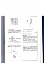
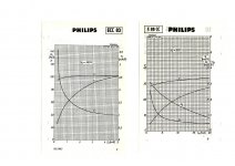
If you compare these two diagrams below, you'll see why I prefer the 5751/ECC83/12AX7 types at low current Ia for the input RIAA-stage. Of course you must arrange it in a SRPP or CF configuration, not to load it down by the RIAA EQ-network.
JohanB
Attachments
Well, the ECC83 is notorious for grid current, so anything is a step up. 😀
Grid current issues are easily seen in distortion spectra and I can't seem to turn that up in any of the data I've taken with my own (D3a input) preamp, which is biased to 1.2V cathode-to-grid. I'm not clear on the relevance of data with a 47k source impedance, since this does not represent a cartridge. It IS relevant for the second tube in passive EQ designs, but that's very dependent on the EQ component values.
Grid current issues are easily seen in distortion spectra and I can't seem to turn that up in any of the data I've taken with my own (D3a input) preamp, which is biased to 1.2V cathode-to-grid. I'm not clear on the relevance of data with a 47k source impedance, since this does not represent a cartridge. It IS relevant for the second tube in passive EQ designs, but that's very dependent on the EQ component values.
I used a mu follower for 6N2PEV which is a low grid current 12AX7 in a phono once because I had them. I wonder about injecting enough grid current into a direct coupled high MC or MM (200R-say 3K) and biasing its motor or not. Could a high gm input tube produce enough to saturate such carts?
Salas, remember you're talking about something less than a microamp. With an MM (or transformer), that corresponds to less than a millivolt. That's not much bias...
Agreed. I haven't seen any issues with grid current when biasing to -1.5V or more. The D3a (IMO, the best easily-available tube for the first stage) has more grid current issues, but since the source impedance is so low (1k for an MM or a stepped-up MC), it becomes a non-problem.
The source impedance gets very high in the treble from a MM-PU or MC/transformer combination. Not 1 KOhm!!
Se the attached National Semiconductor paper in my earlier post. It hits a combined 42!! KOhm in the treble.
Again, test with a 47 KOhm generator impedance (instead of 600) to trace this kind of distorsion.
JohanB
Salas, remember you're talking about something less than a microamp. With an MM (or transformer), that corresponds to less than a millivolt. That's not much bias...
I would much like its totally innocuous because there are so many Grados and Hi-MC in a good price/fidelity ratio out there... And skipping the input Tx hunt and cost.
Also, I'm curious about the "higher gm means higher grid current" assertion. I would think that this would be a matter of mu much more so than gm. For example, the E88CC is rated at 0.1uA max ig at 1.3V bias, compared to the E83CC's doubled grid current rating of 0.2uA at 2V bias.
Must be more a matter of distances and insulation quality also, because there are special low grid current tube models of some same basic types.
Hello,
The low noise high gm tubes developed for RF were used as grounded grid amplifiers. It seems that using them in grounded cathode circuits is not using them to full advantage?
DT
All just for fun!
The low noise high gm tubes developed for RF were used as grounded grid amplifiers. It seems that using them in grounded cathode circuits is not using them to full advantage?
DT
All just for fun!
Lookie! Grandpa scientist investigated it in 1930. http://cos.cumt.edu.cn/jpkc/dxwl/zl/zl1/Physical Review Classics/science/014.pdf
Grid current is caused by a number of things. Distance from the cathode is one of them: close spacing means more electron current to the grid but also higher gm. Frame grid valves like ECC88 have very close spacing. Some E83CC are also frame grid. Gold plating the grid helps prevent reverse electron current if the grid gets hot.
Residual gas levels affect the ionic grid current.
To achieve a particular mu and gm at a particular anode current (i.e. to make a particular valve type) there are many parameters you can vary (such as electrode sizes and spacings, shape, grid winding pitch). Some of these will have secondary effects, such as more/less grid current or distortion. So, other things being equal, I believe that higher gm tends to lead to higher grid current. Higher gm certainly narrows the window between grid current and cutoff. Other things are not always equal.
This is true, and easily measured. Grid currents in the ECC82 and ECC83 are practically identical. Although the ECC82 has twice the gm, it has one fifth the mu, so it evens out.So, other things being equal, I believe that higher gm tends to lead to higher grid current. Higher gm certainly narrows the window between grid current and cutoff.
The ECC88 has high gm and fairly high mu too, and sees about eight times more grid current as a consequence. Hence it has to be biased far beyond Vgk = -1V to avoid grid current distortion. The comparison is made worse when you consider that the ECC88 usually operates with a much lower anode voltage than the 82/3, and this too keeps grid current high.
Last edited:
- Status
- Not open for further replies.
- Home
- Amplifiers
- Tubes / Valves
- 12AU7 Phono Stage