Sorry to hear that Chris.Thanks. I googled light bulb tester and what I saw was simply a mains bulb in series with the AC, is that all?
Thinking new build of the blown board will be best, I would never trust the damaged one and I really don't want to blow my expensive speaker drivers.
Darn, was so pleased the first channel came up first time. Should have taken more time over it. Still, of the many amps I have built over the years this is the first failure.
Thanks. I googled light bulb tester and what I saw was simply a mains bulb in series with the AC, is that all?
Yes, MBT (Mains Bulb Tester) is a normal incandescent bulb in series with "Line".
I wouldn't power up any of builds without it. even when I make simplest of changes, I would still power it up with MBT. Very handy to have.
Powering Your Radio Safely with a Dim-bulb Tester
regards
Prasi
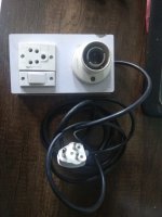
edit: here is a pic of my compact MBT. The plug is connected to the mains socket.
The mains line is connected to bulb and then it goes to the switch. and from switch to the socket on the MBT.
Power for DUT (Device Under Test) is taken from the socket on MBT.
Attachments
Last edited:
Ok I'm near ready to test one AX14 channel.
I checked all my transistors to make sure none had continuity from the legs to all bolts and heatsink. All clear!
I checked all my transistors to make sure none had continuity from the legs to all bolts and heatsink. All clear!
A simplified assembly for help 🙂
Attachments
Thanks mate!
I do have the parts to make one, I've just been lazy. I also have a dual 30vdc 10a power supply arriving this week as well that I could use to limit current.
I still have to solder in the transistors in the second board.
It's going to be fun making the amp enclosure for it all. Haha


.jpg")

One dead channel!
OK, so knocked up a light bulb tester. Tried it on the good channel first. 75W bulb, briefly lights as PS cap bank charges then pretty much goes out, think I need a smaller wattage bulb but most of my bulbs are LED these days!
Replaced 2.2uf caps, D4,5 and fuses on the blown board. Powered up via light bulb tester, bulb behaved the same as with the good channel. However I was never able to get the voltage across any of the .33ohm resistors above .8mv. I think I will call it a day with this one and build a replacement board. I could go through and check voltages around the board but given there must be damage I am not sure I could trust it even if I can fix it.
Sounds like they are behaving properly. You can’t set bias with DBT in series, as it takes the current.
If you don’t care - why not go without the DBT on the repaired channel ONLY.
I think it will be fine, just run it w/o speakers long enough to know it is good and safe.
If you don’t care - why not go without the DBT on the repaired channel ONLY.
I think it will be fine, just run it w/o speakers long enough to know it is good and safe.
Last edited:
Sounds like they are behaving properly. You can’t set bias with DBT in series, as it takes the current.
If you don’t care - why not go without the DBT on the repaired channel ONLY.
I think it will be fine, just run it w/o speakers long enough to know it is good and safe.
You are right, nice and stable with 11mv on the .33ohm resistors and 10mv across speaker output.
Thanks for that, hopefully saved me a rebuild. I will leave it running under test for 24-48 hours.
The fuses and the diodes saved you. That is what they are there for. I was hoping you didn't give up.
You are right, nice and stable with 11mv on the .33ohm resistors and 10mv across speaker output.
Thanks for that, hopefully saved me a rebuild. I will leave it running under test for 24-48 hours.
Glad it worked out! Let me know your thoughts on the sound, I am trying to decide my next build.
Glad it worked out! Let me know your thoughts on the sound, I am trying to decide my next build.
Thanks.
Yes, will do. It is destined to drive a B&G Neo8 (possibly to be upgraded to a Neo10) in an active 3-way system. Obviously that will complicate my judgement of sound quality. Will probably try it with some full range speakers first tho.
Current Limiter completed!
Only thing is maximum watt lamp I can get atm is 77w. I tested my transformer and pay and it lights up for a second then goes off.
Should I proceed and hook up my amp board to the PSU?


Only thing is maximum watt lamp I can get atm is 77w. I tested my transformer and pay and it lights up for a second then goes off.
Should I proceed and hook up my amp board to the PSU?
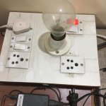
Ok so I got some balls and thought I would try it out before I went to bed lol.
I had multimeters in series with each rail.
I installed 0.1A fuses in the board for safety.
I also have the Bias Pot set All the way counter clockwise to what I believe near zero.
My DMM's showed 1.120A and -1.139A
The later DMM reading for the negative rail is the more accurate DMM.
Cool picture hey lol
So do you think I am safe to put in bigger fuses?
1.2 A is too high and your bulb is lighting very bright.
The filament should hardly be visible in orange color when amp is idling.
Turn down the bias pot, amp should not be consuming more than 50-100 mA.
The filament should hardly be visible in orange color when amp is idling.
Turn down the bias pot, amp should not be consuming more than 50-100 mA.
Last edited:
Should I have an earth wire here like this?1.2 A is too high and your bulb is lighting very bright.
The filament should hardly be visible in orange color when amp is idling.
Turn down the bias pot, amp should not be consuming more than 50-100 mA.

You do not need to run ground from IEC to PSU, IEC ground is for safety and ties to the metal chassis to ensure it blows fuse rather than go live.
Have you connected the dmm across the 0.33r and checked actual bias? I would connect a dmm (keeping the low fuses installed and turn it on for a few seconds - only to see bias.
If it is high, you turned the trimmer the wrong way, turn off quickly and turn the trimmer 2-3 turns the opposite direction and try again.
If it went down, you need to turn trimmer more in that direction if it stayed same or higher - you have a problem.
Turn it off quickly and go back through your connections and soldering.
I think everything is all good. Only drawing 0.01a now!You do not need to run ground from IEC to PSU, IEC ground is for safety and ties to the metal chassis to ensure it blows fuse rather than go live.
Have you connected the dmm across the 0.33r and checked actual bias? I would connect a dmm (keeping the low fuses installed and turn it on for a few seconds - only to see bias.
If it is high, you turned the trimmer the wrong way, turn off quickly and turn the trimmer 2-3 turns the opposite direction and try again.
If it went down, you need to turn trimmer more in that direction if it stayed same or higher - you have a problem.
Turn it off quickly and go back through your connections and soldering.
My theory was I had the trimmer pot set to basically zero (All the way anti clockwise) till it clicked. All I changed was wound it 10 turns Clockwise.
On restart up also added 10ohm resistors in series with the rails to the board and tested again and then without the resistors.

- Home
- Amplifiers
- Solid State
- 100W Ultimate Fidelity Amplifier