So how do I exactly check bias?You do not need to run ground from IEC to PSU, IEC ground is for safety and ties to the metal chassis to ensure it blows fuse rather than go live.
Have you connected the dmm across the 0.33r and checked actual bias? I would connect a dmm (keeping the low fuses installed and turn it on for a few seconds - only to see bias.
If it is high, you turned the trimmer the wrong way, turn off quickly and turn the trimmer 2-3 turns the opposite direction and try again.
If it went down, you need to turn trimmer more in that direction if it stayed same or higher - you have a problem.
Turn it off quickly and go back through your connections and soldering.
So how do I exactly check bias?
normally you would put the dmm probes across one of the 0.33r resistors (emitter resistor) and adjust the trimmer until you get 10-12mV across that resistor.
With those tombstone resistors, its hard to probe those leads.
Check pic on post#11613 - it shows how to connect between emitter of transistor and other dmm lead on the speaker output tab. nothing on the input and nothing else connected to the output.
Thanks. I tested and wasn't getting anything happening on my DMM. I checked my diodes and Ive blown 3 that I see. I will replace them all tomorrow and try again. Thanks lads.normally you would put the dmm probes across one of the 0.33r resistors (emitter resistor) and adjust the trimmer until you get 10-12mV across that resistor.
With those tombstone resistors, its hard to probe those leads.
Check pic on post#11613 - it shows how to connect between emitter of transistor and other dmm lead on the speaker output tab. nothing on the input and nothing else connected to the output.
you can also check bias by connecting red probe to the "emitter" lead of the output device and black probe to "output" connector.
Its same thing as connecting across the emitter resistors.
be careful and dont let it touch anything else nearby.
regards
Prasi
Its same thing as connecting across the emitter resistors.
be careful and dont let it touch anything else nearby.
regards
Prasi
I wonder what we'll use in place of incandescent bulbs when they're basically disappeared from the face of this earth.
Where I am, they're no longer available and haven't been for years now.
At first the replacements were those expensive low power bulbs, no longer incandescent, and supposedly long life (big lie), and now it's all led bulbs, even lower powered, but none of that can be used for our purposes instead of incandescent bulbs.
Finding an alternative won't be that easy, and as cheap.
I wonder what we'll use in place of incandescent bulbs when they're basically disappeared from the face of this earth.
Where I am, they're no longer available and haven't been for years now.
At first the replacements were those expensive low power bulbs, no longer incandescent, and supposedly long life (big lie), and now it's all led bulbs, even lower powered, but none of that can be used for our purposes instead of incandescent bulbs.
Finding an alternative won't be that easy, and as cheap.
Use 150R/50W resistor instead bulb.
Use 150R/50W resistor instead bulb.
By feeling the temperature, may be? if it doesnt get hot, everything is ok. gets hot= something wrong.
If you are in France you go therePhilips Incandescent Standard 60W E27 230V A55 | LampesDirectI wonder what we'll use in place of incandescent bulbs when they're basically disappeared from the face of this earth.
Where I am, they're no longer available and haven't been for years now.
At first the replacements were those expensive low power bulbs, no longer incandescent, and supposedly long life (big lie), and now it's all led bulbs, even lower powered, but none of that can be used for our purposes instead of incandescent bulbs.
Finding an alternative won't be that easy, and as cheap.
ou en rouge 100wPhilips R95 IR 100W E27 230V Rouge | LampesDirect
Last edited:
By feeling the temperature, may be? if it doesnt get hot, everything is ok. gets hot= something wrong.
If there is low voltage drop everything is ok, if there is high voltage drop it get hot but circuit is protect of demage.
If there is low voltage drop everything is ok, if there is high voltage drop it get hot but circuit is protect of demage.
Someone who can calculate and post a schematic using an op amplifier for resistor canceling via a relay when voltage drop on the resistor is low? 😉
Someone who can calculate and post a schematic using an op amplifier for resistor canceling via a relay when voltage drop on the resistor is low? 😉
This will be soft-start, relay can be drive from DC protect.
I switched back to BC546's after having some trouble getting the amp to work with the 2n5551's. The KSC3503 and KSA1381's are still there instead of the BD139/140's though. Bias current set at 175mA as measured through the pair of 0.47R source resistors. 52v rails provided by Abletec SMPS and CRC filter.
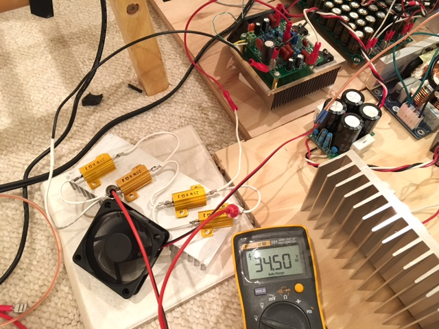
I mounted the FH9HV onto an old Pentium solid copper heatsink and connected a 100w dummy load comprised of four 8R 25w aluminum shell power resistors in series parallel. They measure 10ohms when hot though.
Amp connected to 52v SMPS and CRC PSU filter, small noiseless fan used to augment cooling:
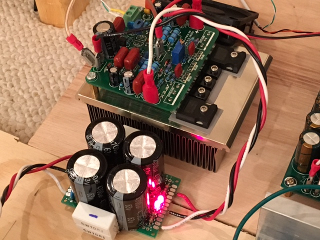
Closeup of amp connected and playing music:

Stress test using 1kHz sine wave at max input before clipping gives 34.5v rms. For a 10R load that is about 120 watts. It was steady from 30Hz to 10kHz (tested at 20, 30, 100, 1000, 2000, 10kHz). At 20Hz it drooped to 34.1v, otherwise rock steady output rms voltage output vs frequency. The amp was able to sustain this level of output no problem. I ran the test for 15 minutes. The resistors were giving off a smell, and the heatsink was outgassing some of the leftover grease/cutting fluid used for the tapping operation. But heatsink could be touched for 10 seconds or so when fan is on.
How does it sound? Excellent - still one of the best sounding amps I have. With 52v rails, I have to say, the bass is very powerful and crisp. Clean, undistorted bass with a deep reach. Very nice. Mids and highs still clear and no sibillance or fatigue.
I think this HV version is a pretty compact 120w class amp. The Chinese hexFETs held their own - which leads me to believe they are real. No mini-die fake can hold up to that kind of test.
I highly recommend this build - easy amp to make and swapping out the drivers and using 63v rated electrolytic caps gives it some much needed power reserve.
I guess Jay was right - this amp and hexFET shouldn't have any problems running at these voltages.
Are C3503 and A1381 replaceable with MJE340&350?
Regards.
Mr. Mile,
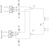
Can this be used as a passive source selector for preamps?
Based on B1 buffer schematics.
RCA- https://www.cui.com/product/resource/rcj-22xx.pdf
Switch- https://uk.farnell.com/multicomp/1ad1t2b4m7re/switch-pcb-dpdt-on-on/dp/1550173
regards
Prasi
Can this be used as a passive source selector for preamps?
Based on B1 buffer schematics.
RCA- https://www.cui.com/product/resource/rcj-22xx.pdf
Switch- https://uk.farnell.com/multicomp/1ad1t2b4m7re/switch-pcb-dpdt-on-on/dp/1550173
regards
Prasi
Attachments

Thanks guys for the help. I got the AX14 channel working. I had the bias pot set too low and was drawing too much current. Should have had it fully clockwise and then to adjust it slowly spin it anti clockwise till I hit 10 - 12mV.
Tomorrow I will use my scope and function generator and have a bit of a mess with it.
Thanks for the splice file it helped me check the voltages.
Had a quick play with my speaker and sounds pretty damn good so far.
Also another thing I noticed I cant feel any heat on the heatsink after 1.5 hours playing music. Si I guess that means I can probably go a lot more higher on my bias?
Thanks again for the help!
your heatsink is massive and also class AB amps with correct bias dont produce much heat, especially if you are listening at normal levels.
total heat would be approx 3-4 W.
optimal bias current is approx 30mA. you may run it higher if you feel so, may not bring about much improvement.
total heat would be approx 3-4 W.
optimal bias current is approx 30mA. you may run it higher if you feel so, may not bring about much improvement.
Started of with one channel, have doubt regarding the C1 - can I use 10uf 50v capacitor ?
Regards
Raj


Regards
Raj
YesStarted of with one channel, have doubt regarding the C1 - can I use 10uf 50v capacitor ?
Regards
Raj
View attachment 773583View attachment 773584
Started of with one channel, have doubt regarding the C1 - can I use 10uf 50v capacitor ?
Regards
Raj
View attachment 773583View attachment 773584
Please populate R23 from bottom.
yes, the muse non-polar caps are good and especially made for audio.
regards
Prasi
AX14 hum
AX14 now complete and in a case. Makes music (just some cheap test speakers at the moment) but also rather a lot of hum.
I am using Prasi's board with D6/7, C13 and R23 all installed. Looking at the options for earthing that Prasi supplied, shorting R23 with a link is probably my best option. The easiest way to achieve that given my setup looks to be running a wire from the input earth connector to the earth on my power supply board. As a test is this a reasonable thing to do?
Never been troubled with hum in any of my previous amps - maybe I was just lucky.
Thanks
- Home
- Amplifiers
- Solid State
- 100W Ultimate Fidelity Amplifier