Hello,
yes, you may.
higher wattage is always better.
but the footprint i have on my pcb, it may be only possible to fit a 0.5W there.
regards
Prasi
yes, you may.
higher wattage is always better.
but the footprint i have on my pcb, it may be only possible to fit a 0.5W there.
regards
Prasi
And what sort of Bias should we aim for and do we leave the output transistors out till we have set the bias?
Hello,
yes, you may.
higher wattage is always better.
but the footprint i have on my pcb, it may be only possible to fit a 0.5W there.
regards
Prasi
Thank you will try to get it or else will use the 2W one
Last edited:
I ended up buying these from Digikey for R23 10ohm 2wThank you will try to get it or else will use the 2W one
FMP200JR-52-10R Yageo | Resistors | DigiKey
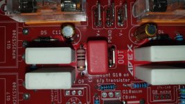
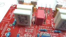
And what sort of Bias should we aim for and do we leave the output transistors out till we have set the bias?
about 50mA would be good. From memory, Mr. Mile recommends about min value of 25mA or 30mA.
It would be convenient and straight forward to set bias with output transistors in place, insulated from and mounted on heatsink .
Last edited:
Everything looks right up to q8 and q9. Make sure they are not faulty and check the pins are correct per the data sheet.
The base of Q11/Q13 should have around 1.1v (+&-).
Where did you buy the transistors from?
..I bought the components here Componenti elettronici. Distributore e negozio online - Transfer Multisort Elektronik , I never had any problems
It looks as though you have a short to ground on the collectors of Q8 and Q9. Have you checked them for that?
... calmly I see again Q8-Q9-Q10 welding and pin out
AX14.
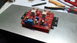
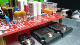
Ok my big output transistors mounted. I'm going to relocate Q10 with wire to the heatsink via a 3 pin pcb quick clip connector. And I have some funny looking heatsinks for the MJE 340/350s.
Does anyone have a photo/schematic of the voltages I should roughly see, please.
I will have 35vdc rails from my 25vac secondarys.
Should I have thiel circuit on the outputs?
Thanks lads for all the help. Almost there now!


Sorry, I don't know what happened there. Here is a corrected file.
Hello Terry,
Could you also attach the spice file and models used.
So people can work out voltages depending upon their supply voltage levels. It will indeed be very helpful to debug every build on their own.
regards
Prasi
AX14.
Ok my big output transistors mounted.
You will be using some mica or silicon insulators on the transistors connected to the heatsink right?
OK, so just theoretically how much damage are you likely to do if you reversed the polarities on the power supply leads to the AX14 board?
Yes, testing my 2nd board I connected the + and - incorrectly, well the marking for the + on the board had gotten a bit hard to see and looked like a - and I rushed things a bit.
Onboard fuses blew straight away then the 2.2uf caps exploded before I could shut the power off. They are before the fuses so not protected.
Obviously fuses and caps need replacing but do you think I likely did any other damage? Everything looks OK, probably try powering up carefully once I replace fuses n caps.
be very careful.
You may have damaged everything. I would discard it and build a new one.
However if you just want to confirm, Use a mains bulb tester to powerup and be at a safe distance. If the bulb lights up brightly, it means the devices are damaged.
You may have damaged everything. I would discard it and build a new one.
However if you just want to confirm, Use a mains bulb tester to powerup and be at a safe distance. If the bulb lights up brightly, it means the devices are damaged.
Hello Terry,
Could you also attach the spice file and models used.
So people can work out voltages depending upon their supply voltage levels. It will indeed be very helpful to debug every build on their own.
regards
Prasi
Hopefully this will help.
Attachments
AX14.
Ok my big output transistors mounted. I'm going to relocate Q10 with wire to the heatsink via a 3 pin pcb quick clip connector. And I have some funny looking heatsinks for the MJE 340/350s.
Does anyone have a photo/schematic of the voltages I should roughly see, please.
I will have 35vdc rails from my 25vac secondarys.
Should I have thiel circuit on the outputs?
Thanks lads for all the help. Almost there now!
View attachment 772555View attachment 772556View attachment 772557
This is with35V rails.
Attachments
OK, so just theoretically how much damage are you likely to do if you reversed the polarities on the power supply leads to the AX14 board?
Yes, testing my 2nd board I connected the + and - incorrectly, well the marking for the + on the board had gotten a bit hard to see and looked like a - and I rushed things a bit.
Onboard fuses blew straight away then the 2.2uf caps exploded before I could shut the power off. They are before the fuses so not protected.
Obviously fuses and caps need replacing but do you think I likely did any other damage? Everything looks OK, probably try powering up carefully once I replace fuses n caps.
If the fuses blew quickly, D5 and D5 may have saved you. You may have to replace them though. It's worth trying it out with a light bulb tester in series with the AC input.
be very careful.
You may have damaged everything. I would discard it and build a new one.
However if you just want to confirm, Use a mains bulb tester to powerup and be at a safe distance. If the bulb lights up brightly, it means the devices are damaged.
Thanks. I googled light bulb tester and what I saw was simply a mains bulb in series with the AC, is that all?
Thinking new build of the blown board will be best, I would never trust the damaged one and I really don't want to blow my expensive speaker drivers.
Darn, was so pleased the first channel came up first time. Should have taken more time over it. Still, of the many amps I have built over the years this is the first failure.
Hi all,
In FH9, T3, ie, MPSA92 running rather hot is it normal ? Does it need a heat sink ? Amp is running fine.
Thanks and regards.
Anoop.
In FH9, T3, ie, MPSA92 running rather hot is it normal ? Does it need a heat sink ? Amp is running fine.
Thanks and regards.
Anoop.
- Home
- Amplifiers
- Solid State
- 100W Ultimate Fidelity Amplifier

