Hi guys,
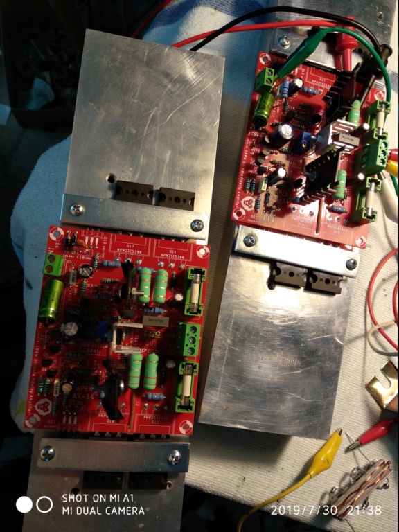
I finished apex ax 14, I tried to set BIAS but I don't understand ... the scan on the tester (mV) is stopped at zero ... in spite of rotating potentiometer P1, down and up. I connected the tester to resistance 0R33......😕
pl check following.
1. Input gnd is connected either on PCB via a 10ohm R23 resistor or separate wire from input gnd to psu gnd.
2. check whether pot resistance is changing when screw is turned. it might be blown.
3. be careful with ceramic 50V cap across drivers. they might have blown and caused oscillation in driver. recommend to use 200v npo/c0g MLCC.
4. ensure all output devices are isolated from heatsink.
regards
Prasi
Last edited:
Look post 4247.
There are measurements from a functional AX14.
Mound bd139 on main heatshink using cables.Pay attention for correct ECB connection!
Measure voltages from your's and compere.
Start from the input transistors pair.
Good luck!
There are measurements from a functional AX14.
Mound bd139 on main heatshink using cables.Pay attention for correct ECB connection!
Measure voltages from your's and compere.
Start from the input transistors pair.
Good luck!
Last edited:
..I built two of these PCB ax 14, both have the same problem, BIAS did not come to a standstill at zero !! I verified the operation P1 is ok, BD139 is on heat sink with insulation, the welds seem ok .... the PCB is very simple ... the margins of error are low .... I have not yet found the problem😕
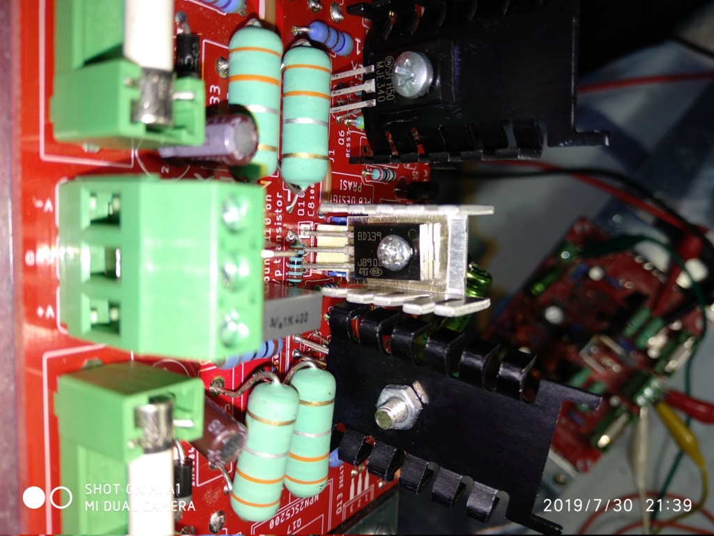
You misunderstand - BD139 needs to be mounted on an output transistor or share the same heat sink as the output transistor.
Have you measured any voltages? Do you have rail voltage after the fuses? Is there rail voltage waiting at the output transistors?
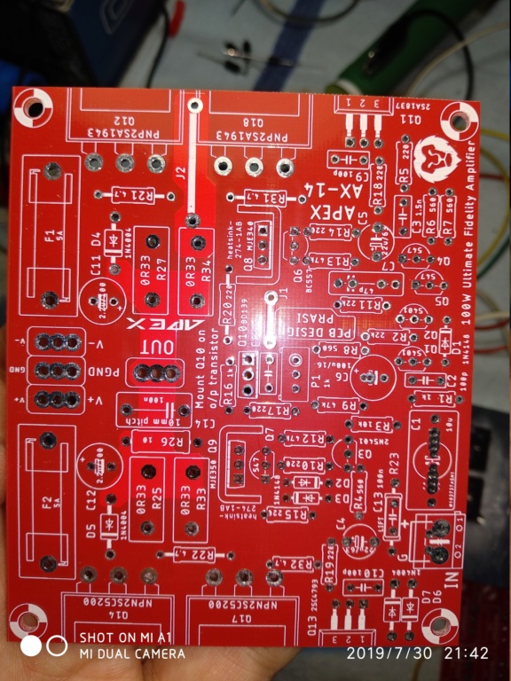
Best thing for you to do is print the schematic, measure points on the circuit referencing Ground and write those values. Then upload a copy so someone might have enough information to be able to help.
Have you measured any voltages? Do you have rail voltage after the fuses? Is there rail voltage waiting at the output transistors?
Best thing for you to do is print the schematic, measure points on the circuit referencing Ground and write those values. Then upload a copy so someone might have enough information to be able to help.
You misunderstand - BD139 needs to be mounted on an output transistor or share the same heat sink as the output transistor.
Have you measured any voltages? Do you have rail voltage after the fuses? Is there rail voltage waiting at the output transistors?
Best thing for you to do is print the schematic, measure points on the circuit referencing Ground and write those values. Then upload a copy so someone might have enough information to be able to help.
.... soon I will proceed with the measurements and publish the schematic of them. I move the BD139 on the transistor sink ... thanks for advice
You mention the bias no coming to “0”, which it shouldn’t be zero.
Are you saying you get no voltage across the resistor? Or that it is very small or large voltage?
What exactly are you measuring (in mV)?
Maybe just me not understanding what you are trying to explain.
Are you saying you get no voltage across the resistor? Or that it is very small or large voltage?
What exactly are you measuring (in mV)?
Maybe just me not understanding what you are trying to explain.
You mention the bias no coming to “0”, which it shouldn’t be zero.
Are you saying you get no voltage across the resistor? Or that it is very small or large voltage?
What exactly are you measuring (in mV)?
Maybe just me not understanding what you are trying to explain.
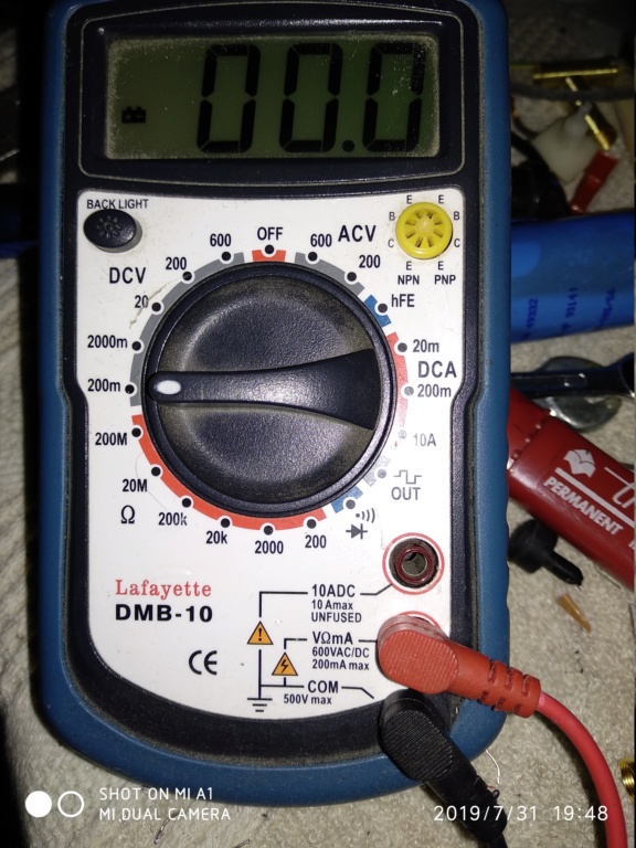
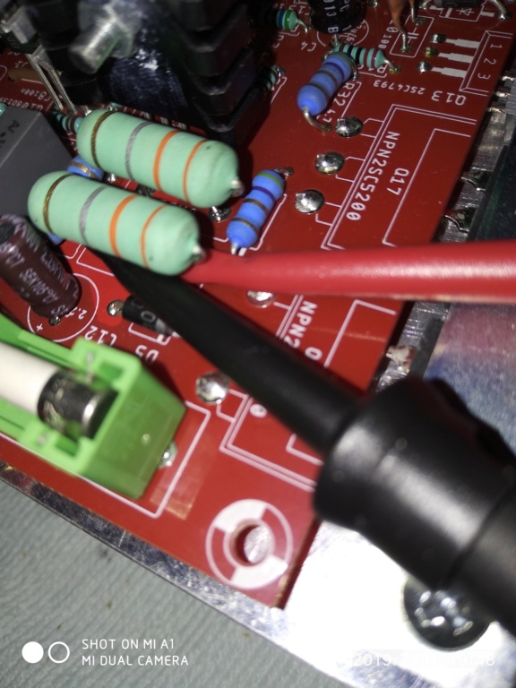
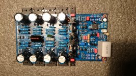
..tester in DCV scale (200mV), like photos, and tips on resistance 0r33 ... something wrong?
Someone else asked but didn’t see you answer.
You do have the power transistors isolated from your heatsink, with a mica or silicon pad?
Since the back is connected to middle pin(drain) - it would not be good if it was not well isolated.
You do have the power transistors isolated from your heatsink, with a mica or silicon pad?
Since the back is connected to middle pin(drain) - it would not be good if it was not well isolated.
Someone else asked but didn’t see you answer.
You do have the power transistors isolated from your heatsink, with a mica or silicon pad?
Since the back is connected to middle pin(drain) - it would not be good if it was not well isolated.
How I can see from the picture the power transistors are not isolated. I can be wrong because hard to see it from your pic. I do not see any white stuff (silicon grease) or mica there. Please measure Ohm between the transistors pinouts without the power on. If they are open they must be replaced because blown.

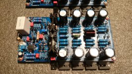
Some more parts arrived today! 0.33r tombstones and some 100pf cornell mica caps. I ordered a DCA75 - Atlas DCA Pro Advanced Semiconductor Analyser to help me pick and match transistors. It has good reviews so will give it a try.
My speaker protection board was completed the other day and tests well. I have put together a quick dual rail psu for testing. I'm hoping my 20,000uf per rail is enough.


My speaker protection board was completed the other day and tests well. I have put together a quick dual rail psu for testing. I'm hoping my 20,000uf per rail is enough.
..tester in DCV scale (200mV), like photos, and tips on resistance 0r33 ... something wrong?
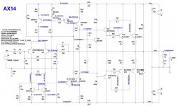
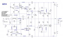
I have run this is LTspice and have printed out a schematic with expected voltages. Hopefully it will help you.
Attachments
Look post 4247.
There are measurements from a functional AX14.
Mound bd139 on main heatshink using cables.Pay attention for correct ECB connection!
Measure voltages from your's and compere.
Start from the input transistors pair.
Good luck!
Are you seeing this?
I have run this is LTspice and have printed out a schematic with expected voltages. Hopefully it will help you.
This is awesome and a huge help to everyone (incl. me!!!). I wish there was a “like” button on here - Thanks!
I have run this is LTspice and have printed out a schematic with expected voltages. Hopefully it will help you.
Hello Terry,
Surely it be a lot of help for ax 100 amp.
Thanks for making and posting it.
One thing is, the base voltage of Q16 is showing as 52V.
Could you reconfirm it?
Regards
Prasi
Hello Terry,
Surely it be a lot of help for ax 100 amp.
Thanks for making and posting it.
One thing is, the base voltage of Q16 is showing as 52V.
Could you reconfirm it?
Regards
Prasi
Sorry, I don't know what happened there. Here is a corrected file.
Attachments
Someone else asked but didn’t see you answer.
You do have the power transistors isolated from your heatsink, with a mica or silicon pad?
Since the back is connected to middle pin(drain) - it would not be good if it was not well isolated.
.. certainly, between the transistor and the heatsink or put Mica insulating support ...
Sorry, I don't know what happened there. Here is a corrected file.
..thanks ... I take into consideration how help me ... I try to take measurements
I tested ne555 protect circuit, only shirt circuit protection is not works otherwise all is working.is there any one tested this feature in this circuit
- Home
- Amplifiers
- Solid State
- 100W Ultimate Fidelity Amplifier