help bias !!!
Hi guys,
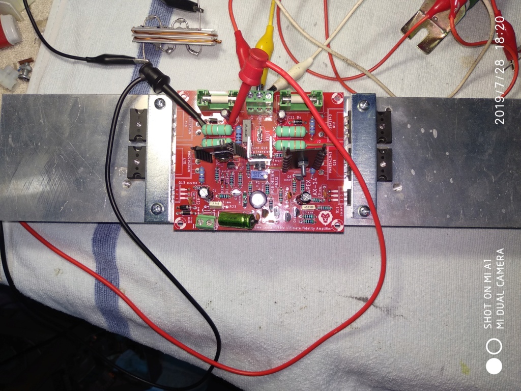
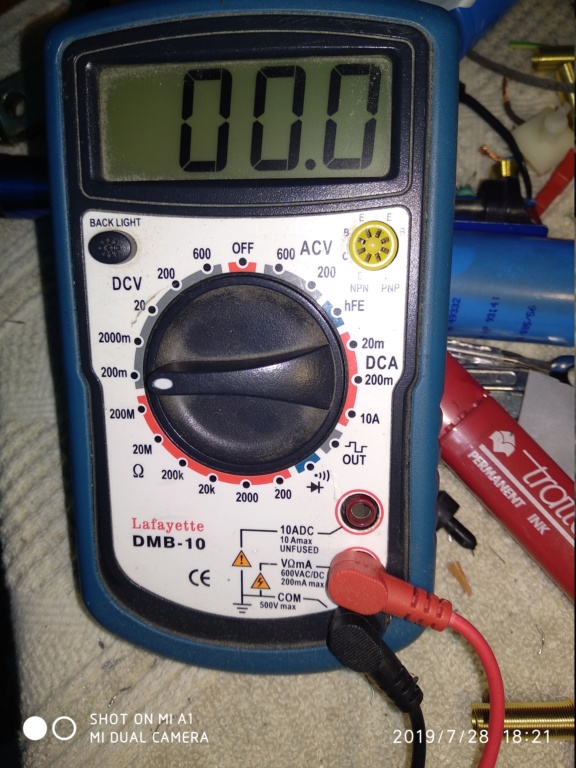
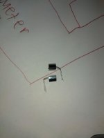
I finished apex ax 14, I tried to set BIAS but I don't understand ... the scan on the tester (mV) is stopped at zero ... in spite of rotating potentiometer P1, down and up. I connected the tester to resistance 0R33......😕
Hi guys,
I finished apex ax 14, I tried to set BIAS but I don't understand ... the scan on the tester (mV) is stopped at zero ... in spite of rotating potentiometer P1, down and up. I connected the tester to resistance 0R33......😕
You need to connect the DMM proves to each side of the resistor leads. Your picture doesn’t look like you have good contact on both resistor wires.
Be careful just turning the pot - you will blow it up pretty quickly.
Be careful just turning the pot - you will blow it up pretty quickly.
Only thing with Q1 and Q2 being coupled together is they are not back to back like they are in the Honey Badger Amplifier. So should I just have Q1 spoon Q2?
View attachment 770913View attachment 770914
Do this as per photo.
Attachments
Last edited:
Hi guys,
I finished apex ax 14, I tried to set BIAS but I don't understand ... the scan on the tester (mV) is stopped at zero ... in spite of rotating potentiometer P1, down and up. I connected the tester to resistance 0R33......😕
Connect signal gng to power supply 0v.
What is your +/- voltages? Is anything getting hot? Or are all the transistors cold
my voltage is 55-0-55 .... the transistors remain cold ...
I have however connected it "music" signal ... and it works, even if it seems a little distorted ...
Connect signal gng to power supply 0v.
..but should the input (signal) not be short-circuited?
..but should the input (signal) not be short-circuited?
Input shorted, signal gnd to power supply 0v.
For this test inp, signal gnd, all together to 0v
..but should the input (signal) not be short-circuited?
Yes they should be shorted for testing but you also need a wire from signal ground to star ground on the PSU.
Input shorted, signal gnd to power supply 0v.
For this test inp, signal gnd, all together to 0v
... now I try, actually GND input not connected to 0V power supply
My Practice
For measuring Bias you can clamp one Tip to Speaker Out position
The other Tip you can point to point test every 0,33 Ohm resistor.
Only little thought, maybe helpful.
I hope all will work fine without bigger problems and you can enjoy AX-14 music.
For measuring Bias you can clamp one Tip to Speaker Out position
The other Tip you can point to point test every 0,33 Ohm resistor.
Only little thought, maybe helpful.
I hope all will work fine without bigger problems and you can enjoy AX-14 music.
..I connect GND input to 0V power supply..nothing BIAS stop at zero mV .. at this point I tried everything for everything, I screwed up the Potentiometer P1 ... no BIAS stationary at zero and cold transistors ??
What schematic you have follow?
Post here exactly what you done.
.. I confirm, the project I built is that of Prasi ..
https: //www.diyaudio.com/forums/solid-state/164093-100w-ultimate-fidelity-amplifier-post5846902.html
I will go out at that point 😱 thimios is the man with much more practice in measuring and analysis.
Prasi's schematic and layout is here: #11462
No no, everyone can help!
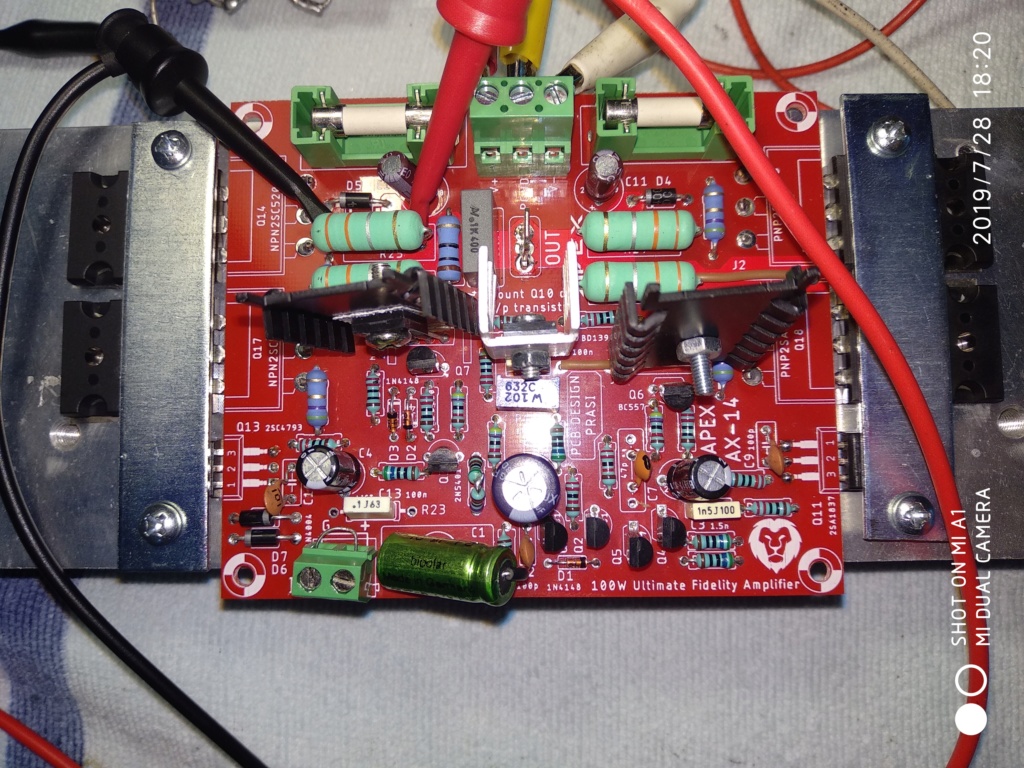
I think that he must examine the board for wrong resistors value placed.
You are right thimios🙂, i have seen in mprivitera second pic he has not placed R23- gnd lift, 10 Ohm, or underneath?
But that's not real he couldn#t set up Bias.
Some bad soldering points, maybe?
Measuring B-E Voltages on each Transistor- conducting?
mprivitera😛rint the schematic and make a notice of every measured point and send it here, only one proposal.
So other members can help more detailed.
Maybe you can start with Q10 measuring C-E Voltage and B-E Voltage.
B-E Voltage should change by moving p1 1k bias trimmpot, is that right, thimios?
- Home
- Amplifiers
- Solid State
- 100W Ultimate Fidelity Amplifier