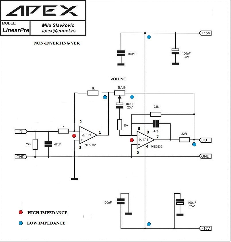
Interesting...out of all the op-amp circuits I've built, I've never tried using the inverting pins on any of them.
Looks like the 100uF cap keeps DC from entering the volume pot and isolates the pot's changing impedance from the input.
If you have a Sprint file for it, I would love to try it.
Also, do you have a Sprint file for a high quality PS for the preamp?
Thanks...
Looks like the 100uF cap keeps DC from entering the volume pot and isolates the pot's changing impedance from the input.
If you have a Sprint file for it, I would love to try it.
Also, do you have a Sprint file for a high quality PS for the preamp?
Thanks...
Any idea what is the gain of this pre-amp, and what is the best way to change it (besides volume pot) ?
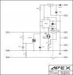
There is a non-inverting version also.
http://www.diyaudio.com/forums/atta...100w-ultimate-fidelity-amplifier-apex-pre.jpg
.
Interesting...out of all the op-amp circuits I've built, I've never tried using the inverting pins on any of them.
Looks like the 100uF cap keeps DC from entering the volume pot and isolates the pot's changing impedance from the input.
If you have a Sprint file for it, I would love to try it.
Also, do you have a Sprint file for a high quality PS for the preamp?
Thanks...
The LinearPre file uses a few SMD parts. The PSU file has the shunt and the classA.
Good luck,
Attachments
The LinearPre file uses a few SMD parts. The PSU file has the shunt and the classA.
Good luck,
No problem with the SMD parts. I'll enlarge the pads slightly to use 1206 capacitors.
Thank you for the files!
Hello all.
Sorry if this is some stupied questions, i have never built a ss amp, just a few tube amp.
But it is time to try 🙂
I'm thinking if building the AX10.
- no need to trim in anything?
- is 2v signal in enough to drive to full power?
- Mouser doesn't have the BD249c and 250c, can i replace with something else?
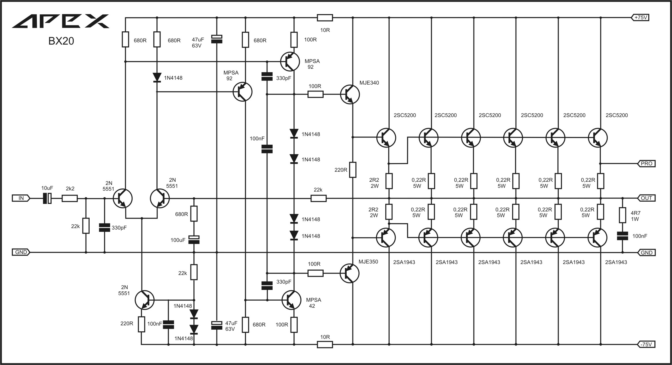
- in the schematic it is a signal called "PRO", what is that?
- can the input ellyt cap be something else? Like a smaller filmcap?
Like i told before, sorry for all the questions...
Best Regards //Daniel
Sorry if this is some stupied questions, i have never built a ss amp, just a few tube amp.
But it is time to try 🙂
I'm thinking if building the AX10.
- no need to trim in anything?
- is 2v signal in enough to drive to full power?
- Mouser doesn't have the BD249c and 250c, can i replace with something else?
- in the schematic it is a signal called "PRO", what is that?
- can the input ellyt cap be something else? Like a smaller filmcap?
Like i told before, sorry for all the questions...
Best Regards //Daniel
Hello all.
Sorry if this is some stupied questions, i have never built a ss amp, just a few tube amp.
But it is time to try 🙂
I'm thinking if building the AX10.
- no need to trim in anything?
- is 2v signal in enough to drive to full power?
- Mouser doesn't have the BD249c and 250c, can i replace with something else?
- in the schematic it is a signal called "PRO", what is that?
- can the input ellyt cap be something else? Like a smaller filmcap?
Like i told before, sorry for all the questions...
Best Regards //Daniel
Hi I will try to answer few of your questions
1. bias- pl refer http://www.diyaudio.com/forums/soli...imate-fidelity-amplifier-656.html#post4643437 . no need to set bias. offset is handled by close matching of i/p pair.
2. I think 0.7-0.8 V is sufficient to drive it to full power (gain-30). someone may confirm this.
3. Still4given has used Onsemi MJW3281/1302, they might be available on mouser.
4. PRO is a pin for connecting to APEX protect PCB's, you may search this thread for many protection PCBs.
5. i/p cap can be a film cap (but will be too big for 10uF). I use bi-polar caps. smaller value film cap might mean higher -3dB frequency point.
regards
Prasi
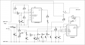
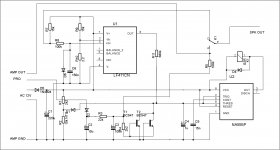
Hi mile, can you check NE555 protection schematic I included elektor impedance sensor.
Is it ok or changes need to be made?
I made changes
Attachments
Two BC547 transistor can be replace with TO92 triac like on this protect.
Attachments
Last edited:
Hi I will try to answer few of your questions
1. bias- pl refer http://www.diyaudio.com/forums/soli...imate-fidelity-amplifier-656.html#post4643437 . no need to set bias. offset is handled by close matching of i/p pair.
2. I think 0.7-0.8 V is sufficient to drive it to full power (gain-30). someone may confirm this.
3. Still4given has used Onsemi MJW3281/1302, they might be available on mouser.
4. PRO is a pin for connecting to APEX protect PCB's, you may search this thread for many protection PCBs.
5. i/p cap can be a film cap (but will be too big for 10uF). I use bi-polar caps. smaller value film cap might mean higher -3dB frequency point.
regards
Prasi
Thanks for the help. I'm looking forward to do this little project.
The MJW3281/1302 is available at Mouser, nice.
Still have a followup question.
1. no need to set bias. offset is handled by close matching of i/p pair.
Do i need to match some tranistors?
Best regards //Daniel
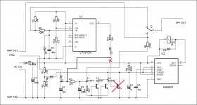
I made changes
Another change.
Attachments
Thanks for the help. I'm looking forward to do this little project.
The MJW3281/1302 is available at Mouser, nice.
Still have a followup question.
1. no need to set bias. offset is handled by close matching of i/p pair.
Do i need to match some tranistors?
Best regards //Daniel
No need to set bias, no need to matching tranistors, just do not test amplifier without heatsink.
Regards
Thanks for the help. I'm looking forward to do this little project.
The MJW3281/1302 is available at Mouser, nice.
Still have a followup question.
1. no need to set bias. offset is handled by close matching of i/p pair.
Do i need to match some tranistors?
Best regards //Daniel
I see, Mr. Mile has already replied to your question and hence deleted my post.
reg
prasi
Last edited:
No need to set bias, no need to matching tranistors, just do not test amplifier without heatsink.
Regards
Thanks apexaudio and prasi 🙂
I will start order parts tomorrow. I already have a 400w toriodal transformer and PSU board (2*6800uf per rail).
Is there any ready pcb to buy? Otherwise i will draw something. Is there any advatage to use smd parts? Will ceramic caps work good for this?
Last questions...for now 🙂
Best regards //Daniel
Is there any ready pcb to buy? Otherwise i will draw something. Is there any advatage to use smd parts? Will ceramic caps work good for this?
There is no PCB available to purchase, though some have posted their layouts if you go back and look.
If you prefer SMD parts, use them. I can't see any advantages to using them in a power amp other than maybe coming out with a smaller PCB.
Ceramic caps will work fine for the smaller caps.
I wouldn't lower the value of the 10uF input cap just to use a MKP or MKT version. It may affect the bass response. Mr. Mile chose that value for a reason.
Thanks apexaudio and prasi 🙂
I will start order parts tomorrow. I already have a 400w toriodal transformer and PSU board (2*6800uf per rail).
Is there any ready pcb to buy? Otherwise i will draw something. Is there any advatage to use smd parts? Will ceramic caps work good for this?
Last questions...for now 🙂
Best regards //Daniel
PCB: http://www.diyaudio.com/forums/soli...imate-fidelity-amplifier-662.html#post4646520 . Only DIY, no PCB on offer.
SMD: is good, but new layout required.
Ceramic: NPO/C0G for small value caps.
Thanks apexaudio and prasi 🙂
I will start order parts tomorrow. I already have a 400w toriodal transformer and PSU board (2*6800uf per rail).
Is there any ready pcb to buy? Otherwise i will draw something. Is there any advatage to use smd parts? Will ceramic caps work good for this?
Last questions...for now 🙂
Best regards //Daniel
Lately I have been using smd for the small value caps where I can. If you look back at the AX10 pic I posted you will see that some of the caps are not installed on the top side. I used smd there. I just soldered them across the tracks in a convenient place. I have had zero issues.
I used the MJWs because I have a lot of them. MJLs or NJWs will work just as well.
ApexAudio,
How many watts is this design good for and what size power supply do you suggest? (VA rating)
I just got a shipment of 10 pairs of 2SC5200 and 2SA1943's for $7 😀
Might be the perfect place to put them to work. Is their a PCB layout for this amp by anyone on the forum yet?
This design uses matched input LTP's to avoid having offset adjustment pot?
Thanks for all your contributions to new amp designs which we are having a good time building.
Since their are so many amps, which ones are your personal favorites for good sound quality at the 50w class? I have heard someone say it is the FX8. Is that true?
Last edited:
- Home
- Amplifiers
- Solid State
- 100W Ultimate Fidelity Amplifier