Ax20 driver
Hi apex, i'm back 😀
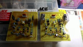
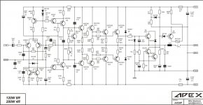
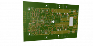
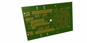
I want to share my ax20 build, hope with 7pairs final transistors can get about 300watt with 45v supply,
He we are
APEX AX20 test using DIY SMPS: http://youtu.be/M2Q_xwZftRU
Some question Sir, how about max Vdc to supply ax20?
This ax20 can use 70vdc with 7pairs final transistors?
Hi apex, i'm back 😀
I want to share my ax20 build, hope with 7pairs final transistors can get about 300watt with 45v supply,
He we are
APEX AX20 test using DIY SMPS: http://youtu.be/M2Q_xwZftRU
Some question Sir, how about max Vdc to supply ax20?
This ax20 can use 70vdc with 7pairs final transistors?
Attachments
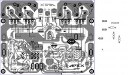
Found oscillation of Apex AX9.It was mistake I made on layout, I connected 47pF to collector and emitter of BD139 and BD140.
I have changed 15v zener to 22v for LME49860. Love sound of this amp on my monitor speaker lots of detail in mids, NX-14 will be replaced with AX9.
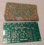
Corrected Layout.
Regards
Thank you for this pcb design.
Regards
Hi apex, i'm back 😀
I want to share my ax20 build, hope with 7pairs final transistors can get about 300watt with 45v supply,
He we are
APEX AX20 test using DIY SMPS: http://youtu.be/M2Q_xwZftRU
Some question Sir, how about max Vdc to supply ax20?
This ax20 can use 70vdc with 7pairs final transistors?
Nice work, AX20 can use +/-70V with 7pairs final transistors.
Regards
Nice work, AX20 can use +/-70V with 7pairs final transistors.
Regards
How about bias to set-up, trimpot only max 320mV on bias to ground with 42Vdc, how to increase bias,what parts to modification?
How about bias to set-up, trimpot only max 320mV on bias to ground with 42Vdc, how to increase bias,what parts to modification?
Replace R16 1k with 1k5
Found oscillation of Apex AX9.
I have changed 15v zener to 22v for LME49860. Love sound of this amp on my monitor speaker lots of detail in mids, NX-14 will be replaced with AX9.
Corrected Layout.
Regards
Hi sonal,
Do the drivers run cool enough that they don't need a heatsink?
Thanks, Terry
Hi Guys,
I've been listening to the A33 most of the day. What a great sounding amp. I had to buy 10 boards and Alex was kind enough to let me share them with folks here on the forum. I have 4 pair available. If any of you are interested in a pair or two, please PM me. I just wanted to prove them first. Alex did a great job on these!
Blessings, Terry
Attachments
Hi Guys,
I've been listening to the A33 most of the day. What a great sounding amp. I had to buy 10 boards and Alex was kind enough to let me share them with folks here on the forum. I have 4 pair available. If any of you are interested in a pair or two, please PM me. I just wanted to prove them first. Alex did a great job on these!
Blessings, Terry
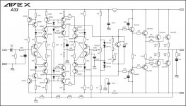
Is this your A33 circuit?
Regards
Attachments

hello sonal kunal
as you can see I already begin the project but give me some time to make sure all is correct I'm also working with another project so as soon is done I will post the PDF files so you can etched unless you don't want to wait I can send you the Sprint Layout file so you can modified the way you want it that is another option if you wish

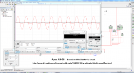
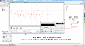
I made a simulation and all seems to work good to 8 ohms load and sine wave of 1KHz 700mVp it give about @8 ohms 193W and the THD is really low according to the software 0.002% t@ 4 ohms load same setting it can give about 387W and THD of 0.002% of course that with 65V rails and also will depend of the power supply too this is just a "approximation" with the software maybe the results in real time might be different
note: this is software simulation in real time might be different results 🙂 I'm aware of that
Regards
Juan
as you can see I already begin the project but give me some time to make sure all is correct I'm also working with another project so as soon is done I will post the PDF files so you can etched unless you don't want to wait I can send you the Sprint Layout file so you can modified the way you want it that is another option if you wish
I made a simulation and all seems to work good to 8 ohms load and sine wave of 1KHz 700mVp it give about @8 ohms 193W and the THD is really low according to the software 0.002% t@ 4 ohms load same setting it can give about 387W and THD of 0.002% of course that with 65V rails and also will depend of the power supply too this is just a "approximation" with the software maybe the results in real time might be different
note: this is software simulation in real time might be different results 🙂 I'm aware of that
Regards
Juan
Attachments
Last edited:
Is this your A33 circuit?
Regards
HI Mile,
Yes, that is it. I see you added the 22p caps and changed the NFB resistor to 47R. That is now what I built except I used MJL4381/4302 for the outputs. Alex also added more caps to the rails but you show the important changes. I really think those comp caps are needed.
Blessings, Terry
Edit ; one other thing. That bias pot needs to be at least 500R, not 220R. I think mine is at about 420R with the bias set to 60mA per output. The bias is way too high at 220R.
Last edited:
HI Mile,
Yes, that is it. I see you added the 22p caps and changed the NFB resistor to 47R. That is now what I built except I used MJL4381/4302 for the outputs. Alex also added more caps to the rails but you show the important changes. I really think those comp caps are needed.
Blessings, Terry
Edit ; one other thing. That bias pot needs to be at least 500R, not 220R. I think mine is at about 420R with the bias set to 60mA per output. The bias is way too high at 220R.
Thanks Terry, 680R+420R=1100R, with 1k resistor 220R pot will be in mid position.
Attachments
Hi Mile,
You are correct. I just measured again and including the 680R resistor I am at 1k1. I suppose if I had changed the resistor to 1k or higher I could have used a 220R pot, however, that is a weird value that I don't have. I stock 200R and 500R in my bin. With the 680R resistor the 500R pot is close to the end of its travel.
Thanks for updating the schematic.
Blessings, Terry
 make me dizzy jejeje

Nice Marc,
You might want to add the 22p comp caps to the C-B of the pre drivers.
Hi still4given,
Place is lefting...adding these caps can be achieved under board.CMS are good NPO are good candidate for purpose.
Marc
Hello guys
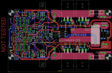
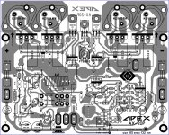
I know the AX-20P is not a new subject but I would like to post here the changes of this layout to turn it from AX-14P to AX-20P I'm almost done with it this take time so I will continue checking to make sure all is correct 🙂
Regards
Juan
I know the AX-20P is not a new subject but I would like to post here the changes of this layout to turn it from AX-14P to AX-20P I'm almost done with it this take time so I will continue checking to make sure all is correct 🙂
Regards
Juan
Attachments

Hi still4given,
Place is lefting...adding these caps can be achieved under board.CMS are good NPO are good candidate for purpose.
Marc
Yes they can. That is what I did on my boards but since you are designing a new layout, why now add pads for them? Your choice of course, it's just a suggestion.
Blessings, Terry
Yes they can. That is what I did on my boards but since you are designing a new layout, why now add pads for them? Your choice of course, it's just a suggestion.
Blessings, Terry
CMS pad wore added, for classical caps there is not enough room.
Marc
- Home
- Amplifiers
- Solid State
- 100W Ultimate Fidelity Amplifier