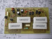
Use 0.22ohm, with +/-33V DC no need for 35A rectifier you can use 10A.this is the best i can get with my phone camera .its night here now.
i havent tested the psu yet.i will connect the 35A rectifier and put back the short circuit protection.
do you suggest 0.22ohm resistors for short circuit protection ? i am using a 24-0-24 volt /200VA transformer which is +-33 volt dc after rectification and smoothing capacitors.
66Vx10A=660W, and your amplifier will be 75W/4ohm with +/-33V rail voltage, 150W for both channels, with 70% eficiency of AB class you need 200W from PSU minimum, I recomended 300W, but 10A rectifier will be OK.
Regards
With 2x24v ac I use this amplifier:
http://www.diyaudio.com/forums/chip-amps/162179-tda7294-stereo-bridge-psu.html
http://www.diyaudio.com/forums/chip-amps/162179-tda7294-stereo-bridge-psu.html

i will put the 8A rectifier and test the psu.but im afraid it will get too hot even at 4 amperes.
do you have tone control circuits?i would like to have one.
do you have tone control circuits?i would like to have one.
You can put heatsink on 8A rectifier, tone control will be shared in thread:i will put the 8A rectifier and test the psu.but im afraid it will get too hot even at 4 amperes.
do you have tone control circuits?i would like to have one.
http://www.diyaudio.com/forums/solid-state/167363-mic-line-eq-preamps.html
Regards
thank you.
by the way, do you have one pair output amplifier design with opamp at the input?
do those amps sound good or is it better to have discrete components at the input instead of opamps?
by the way, do you have one pair output amplifier design with opamp at the input?
do those amps sound good or is it better to have discrete components at the input instead of opamps?
My PA amps use OP-amp at the input on the best possible way. I can't tell you anything about is it better sound than discrete, it's up to you.thank you.
by the way, do you have one pair output amplifier design with opamp at the input?
do those amps sound good or is it better to have discrete components at the input instead of opamps?
Here is schematics of B50 with single darllington pair outputs.
Attachments
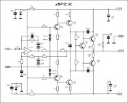
![APEX%20NMOS%20AMP[2].jpg](/community/data/attachments/170/170114-d099a51eb9ec787166351628e9434888.jpg?hash=0JmlHrnseH)
Yes, but this amp from thread: http://www.diyaudio.com/forums/solid-state/163159-150w-mosfet-amplifier-irfp250x2.html I recommended only for fun. If you want nmos amp I sugest to build an ARCAM clone.apex,
does this nchannel design has pcb,or where thread this came?
Regards
NO, IRFP9240 is inexpensiveapex,
do you have this arcam clone design
regards
apex,
can i use darlington output with ultimate fidelity?
using ML3 and this amp,a powerful guitar amp
can i use darlington output with ultimate fidelity?
using ML3 and this amp,a powerful guitar amp
Yes, circuit in post #4, thread:apex,
can i use darlington output with ultimate fidelity?
using ML3 and this amp,a powerful guitar amp
http://www.diyaudio.com/forums/solid-state/162494-amplifier-motherboard.html
Regards
Last edited:
I must say DIY amplifiers are different than comercial amps. Look at the schematics of Pioneer A80 from 80', and you can't find anything better in modern amplifier schematics, and DIY amplifier is not made to competition with comercial in that way, but if you use quality case, heatsinks, speakers terminals, strong transformer and more caps, outputs... than brands, you can get valuable stuff.
I lost this file, do you realy need this pcb?apex,
bottom side pcb
regArds
Um, Mile, I believe the 220R emitter resistor in the VAS current source should be 100R - I have a similar amplifier that sees use as a guitar amplifier.
apex,I lost this file, do you realy need this pcb?
i follow all your model
specialy darlington output
regards
With 100R emitter resistor disipation on VAS transistor will be about 300mW, that's OK for 2N5401/2N5551, but I use 220R like in Carvin PB200.Um, Mile, I believe the 220R emitter resistor in the VAS current source should be 100R - I have a similar amplifier that sees use as a guitar amplifier.
- Home
- Amplifiers
- Solid State
- 100W Ultimate Fidelity Amplifier