I will see if I can find the Sprint file I don't mine to share the files 🙂 maybe you guys can used as reference, I tend to make too big the PCB 😛
Better share Sprint file
Nice to hear that.
I see some interest here in the Abletec +/- 53V power supply, model ALP0400-5301-D
I just stumbled across KestPart's listing for $19.95, which I don't recall being mentioned. Shipping to my home in North Carolina puts it up over eBay's $31.35 (shipped, which I purchased earlier today). However, if your purchase is over $50, the shipping is free... Kinda like "get three for the price of two"... Just a thought.
Disclaimer: I haven't dealt with KestParts, and cannot vouch for them.
Unfortunately this power supply is out of range in Europe (too high shipping costs). But I found a China supply (only 1 output: 48V, 240W) -1 would need 2 of it- for only $24.32 per piece (incl. shipping) here. Has anyone experience with it? Can it be recommended (for test purpose only)?
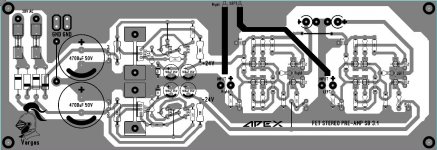
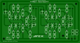
Layout corrected .....😉
hi Alex, still missing connection all 3k3 (bc560) to -24v, is it right ? ty
hi Alex, still missing connection all 3k3 (bc560) to -24v, is it right ? ty
ops, sorry...Vargas pcb correct, only right channel missing connection 3k3 (bc560) to -24v
PCB corect but not good enough
If it isn't good enough, why don't you design a better one and post it?
Then we can all see what a "better" PCB should look like.
Dung...,
If you find mistakes, it is best to identify them and if you have a better layout technique, pls share it with us. Your statement "PCB corect but not good enough" helps know one and makes others think that you are an a$$ 🙂
A few common problems that I see in these deigns.
1) No Linkage or sync between schematic and layout, so checking is old school tedious. This is because know one can agree on a common layout s/w package.
2) I do not see any distortion tests. I am not necessarily saying that they are the holy grail but they can be useful.
3) It is really nice if these deigns are captured in Ltspice, help again in identifying many op parameters.
The cap across the Vbe mutiplier is required. I did a sim of one PA and forgot it. I wondered why the sim'd THD was high, it was the missing Vbe mutiplier cap. Min should be 100n. This is where it would be beneficial to measure distortion with and without it installed to confirm the sim.
xrk971, Good job on getting another sb3.1 going, i sim'd it and sf3.1. sb3.1 was the THD winner but it would nice to actually listen to both of them.
Last edited:
FX8 issue
Hi all,
yesterday, I got my FX8 up and singing on a full range driver.
I had a 4R7 resistor between my PSU and the amplifier
bias was a little bit less 200ma and DC voltage speaker was around 5mv
I was very excited, took pictures to post here, and decided to plug my main speakers.
Today, I don't know what is wrong, turning the resistor does not adjust bias, it is around 20mv, DC speaker is +100mv.
I checked all resistors, looks good.
I need to investigate more but don't know how.
Any help will be very appreciated
many thx!
200mV measured where? How do you know you don't have bias current? Are you using series safety resistor?
Do you have a 4R7 resistor on each rail? Do they measure the same voltage across each of them?
Do you have a 4R7 resistor on each rail? Do they measure the same voltage across each of them?
thanks for answer,
I have 4R7 resistor on each rail.
I think the measured value is in phase with the fact that SK1058 snd SJ162 stay cold
I measure +17mv on the 4R7 resistor located at the + rail
and 25mv on the 4R7 resistor located at the - rail
as far I remember the pot R18 is about 100ohm (but not sure)
Turning the screw change the pot resistor value to 177 ohm but not the voltage at the 4R7 resistor
I also checked all the diods and resistors and if I didn't made a wrong reading, all values look fine.
thanks for your comments
Something is blown. You should measure the same voltage across both 4R7 safety resistors. How much voltage do you see across each of the 10R resistors?
If you can, measure from base to emitter of each BJT. Should be approximately .6V each.
If you can, measure from base to emitter of each BJT. Should be approximately .6V each.
Something is blown. You should measure the same voltage across both 4R7 safety resistors. How much voltage do you see across each of the 10R resistors?
If you can, measure from base to emitter of each BJT. Should be approximately .6V each.
I still have the 4R7 on the rails.
For the 10R resistors, I can't measure the DC voltage.
My multimeter is autorange, and the value always change around 120mv +/- 40mv
Don't know how tm measure voltage of BC & BD transistors. It is soldered. 🙁
Can you measure the voltage across the three 680R resistors? should be close to 1V each.
There are 5 680R
I have around 0.3V , 0.3V, 0.7V on the three 680R resistors on the left. I suspect it is R3 R4 R5.
I think it is 0.7V for R3. it looks linked to BD140 and BC546
What layout are you using. Too many different sets of part numbers to use them without knowing which one you are using. If you are seeing .3V across the two 680R for the LTP then it is not drawing enough current.
- Home
- Amplifiers
- Solid State
- 100W Ultimate Fidelity Amplifier