I don't think you have any hope of hitting that target.sir, can I replace all 5 pair output to 2sc2922/2sa1216 sanken? I want to drive 2 ohms speaker for 70 0 70 v dc rails in apex bx 22..
±70Vdc should allow you to easily hit 56Vpk into 8ohms. That's 200W into 8ohms.
You should manage 400W into 4ohms and 800W into 2ohms.
Expect a genuine 2ohms capable amplifier to give a bit more than 56Vpk. Maybe >58Vpk into 4ohms and >60Vpk into 8ohms.
800W into 2r0 dummy load is equivalent to 56.6Vpk and 28.3Apk
What do you allow for driving a reactive load? Twice that current, or three times that current?
I don't think you have any hope of hitting that target.
±70Vdc should allow you to easily hit 56Vpk into 8ohms. That's 200W into 8ohms.
You should manage 400W into 4ohms and 800W into 2ohms.
Expect a genuine 2ohms capable amplifier to give a bit more than 56Vpk. Maybe >58Vpk into 4ohms and >60Vpk into 8ohms.
800W into 2r0 dummy load is equivalent to 56.6Vpk and 28.3Apk
What do you allow for driving a reactive load? Twice that current, or three times that current?
5*2.5=12.5A (sanken =2.5A at 70v dc).800/56=14.2A...so it is very close ..
Check the temperature de-rated SOA against the transient demand of a reactive load.
It will fail eventually, if not within the first few days.
I would expect a 5pair 200W device output stage to be very reliable giving 400W into 4ohms. But asking for 800W into 2ohms is quite different/onerous.
Unfortunately Sanken don't give any 100ms, nor 1ms, SOA data.
It will fail eventually, if not within the first few days.
I would expect a 5pair 200W device output stage to be very reliable giving 400W into 4ohms. But asking for 800W into 2ohms is quite different/onerous.
Unfortunately Sanken don't give any 100ms, nor 1ms, SOA data.
Last edited:
Check the temperature de-rated SOA against the transient demand of a reactive load.
It will fail eventually, if not within the first few days.
I would expect a 5pair 200W device output stage to be very reliable giving 400W into 4ohms. But asking for 800W into 2ohms is quite different/onerous.
Unfortunately Sanken don't give any 100ms, nor 1ms, SOA data.
understood ,but my question is in sanken at 70v dc the bias current is same as toshiba 5200?actually there is no bias set up pot at apex bx 22.
Last edited:
What?
if I change output directly form toshiba pair to sanken pair in apex bx 22 while other components remains same what will be the effect?? or is there any changes I have to done??
you have to check the design still works.
It may require no changes or many changes.
You become the Designer, instead of the Builder.
It may require no changes or many changes.
You become the Designer, instead of the Builder.
sir, can I replace all 5 pair output to 2sc2922/2sa1216 sanken? I want to drive 2 ohms speaker for 70 0 70 v dc rails in apex bx 22..
Yes you can use sankens to drive 2 ohms, but with large heatsink and fan for cooling.
It's in the Apex Directory thread. But that one is the standard version with BD139/140 drivers.
http://www.diyaudio.com/forums/solid-state/292226-directory-apex-audio-amplifiers.html
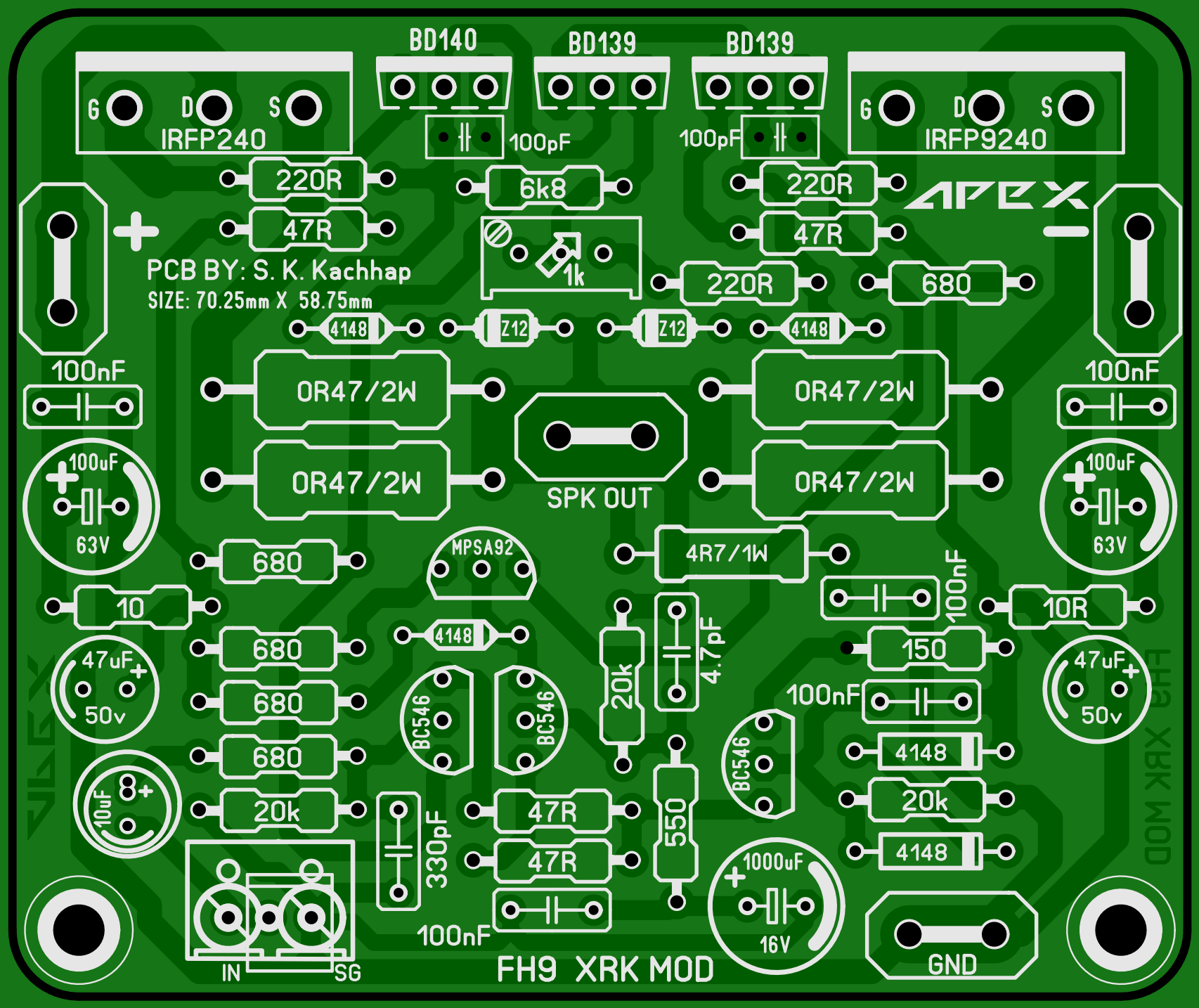
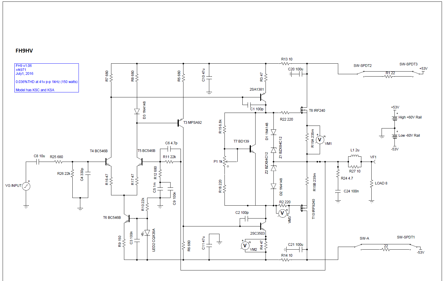
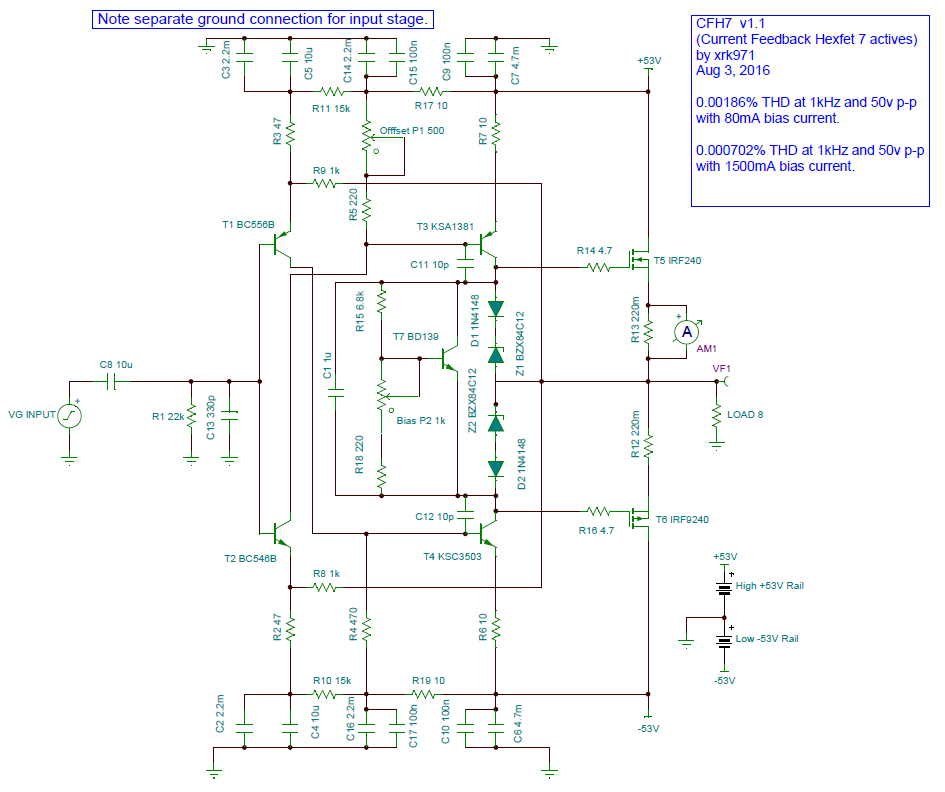
Here is updated schematic with KSC/KSA drivers (note that this is a slightly later version with LED on CCS for LTP - as used on FH11/12 so that is proven to work. Without it works fine too - just no visual indicator it's powered up):
Gerbers and layout here:
http://www.diyaudio.com/forums/soli...imate-fidelity-amplifier-746.html#post4718422
Just replace BD139/140 drivers with KSA/KSC parts and make sure all elco's can handle higher rail voltages.
Clever design. I do have concerns.
1. How do you guarantee there is no cross conduction of the output transistors, ever? If they are both on, massive currents will flow. The gate capacitance of the P channel FET is typically double, so that leg will turn off slower with equal gate stoppers. To prevent cross conduction the deadband must be larger, which causes crossover distortion. This is tricky to solve.
2. What limits the current to the output drive voltage clamp zeners? This should be limited to small currents somehow. Connecting them on the gate side of the gate stopper resistors is a partial solution, but adds parasitics there, which is not good. I prefer to put ferrites at the gate, in addition. This is mandatory for parallel MosFet outputs, IMO. I've seen oscillations in the 50+ MHz range that need to be dealt with.
Thanks for sharing your concerns. But they are definitely not a problem on this amp. I am not sure of the cross conduction issue as many many amp designs use a similar output stage topology. The FH9 and FH9HV has been built by many people and all report good sound. It's one of the easiest amps to build and get working properly. Even the dual output variant, the FH11 has been shown to work well. Terry provides scope traces of clean square waves no oscillations or ringing. I think at least 6 people have built the FH9 and all say it sounds great.
Try it - it sounds fantastic. $24 for 10 PCBs from PCBWay.com and parts costs is about $10ea (or less). Incredible value for the sound quality.
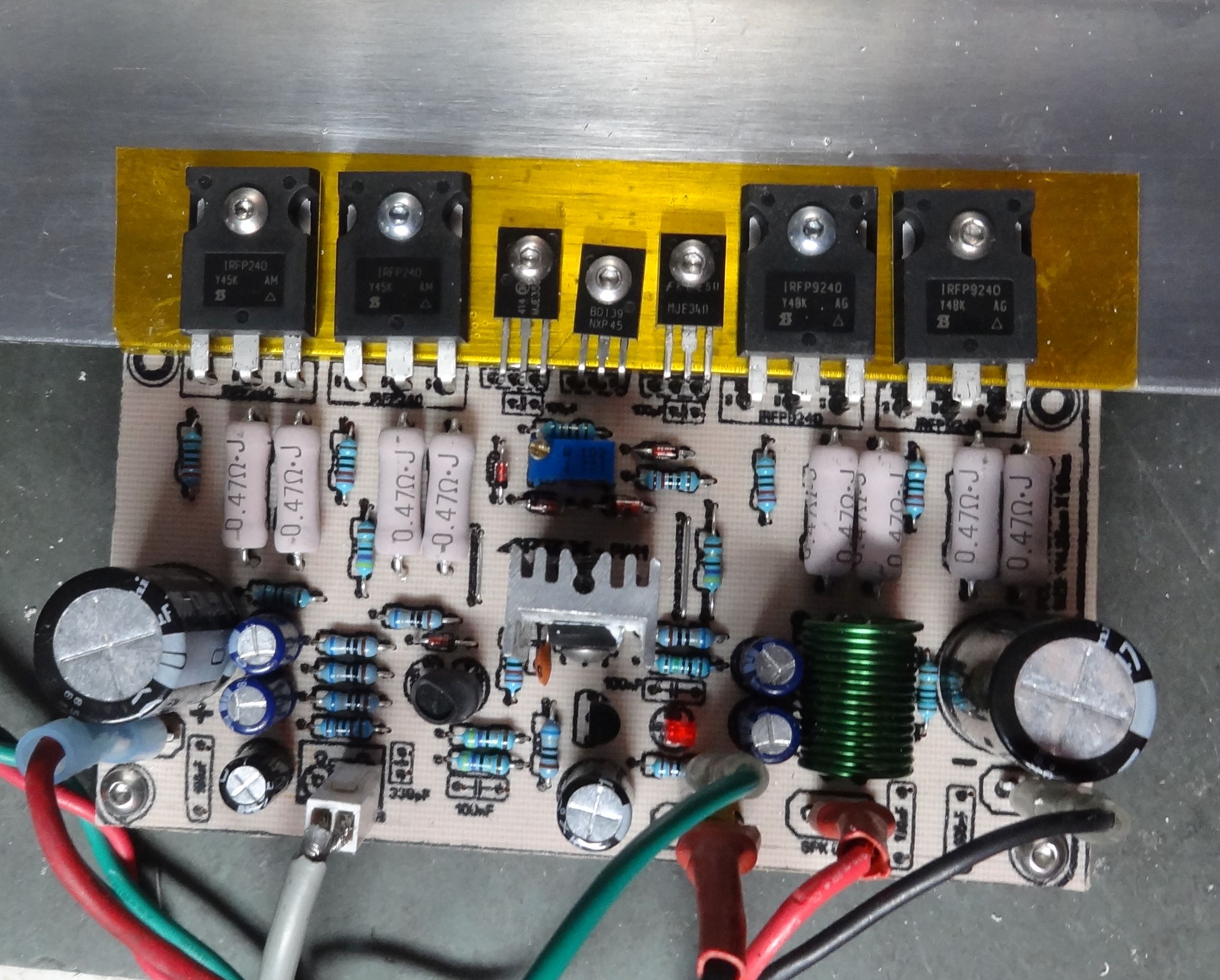
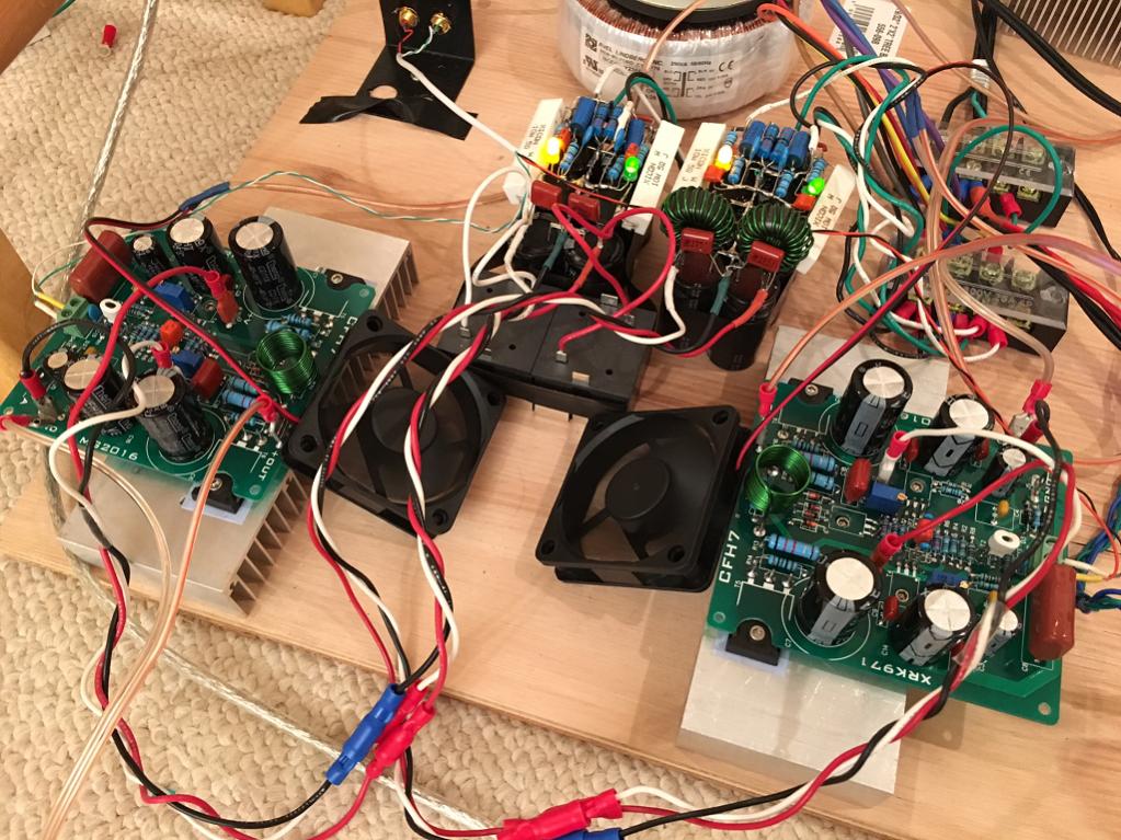
Here is my FH9:
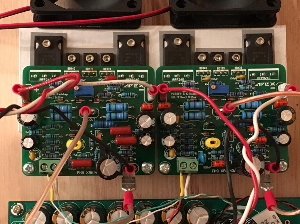
Here is FH9HV (use KSA and KSC drivers for 53v rails):

Here is Terry's FH11 build:
I have the CFH7 that has the same output topology and that works well too (clean square waves up to 100kHz).
Last edited:
Thanks for sharing your concerns. But they are definitely not a problem on this amp.
Hello xrk971.
What is the efficiency of the FH9HV with full power (8Ohm)?
Not sure what you mean by efficiency. I was able to drive a maximum of 120w into a 10R dummy load with 53v rails.
With 8R load maybe 130w max?
With 8R load maybe 130w max?
Not sure what you mean by efficiency. I was able to drive a maximum of 120w into a 10R dummy load with 53v rails.
With 8R load maybe 130w max?
Efficiency is for me ratio of output power / DC power
so, for about 120W output power (10 Ohm) you needed 53V rails and how much DC current?
I did not measure wall plug efficiency - why are you interested in it ? People who care go class D. Class AB will burn off some heat. I would have to hook it up and measure again.
I did not measure wall plug efficiency - why are you interested in it ? People who care go class D. Class AB will burn off some heat. I would have to hook it up and measure again.
xrk971, no wall plug efficiency! That would be before the PSU. I meant DC rails! The reason is very simple: I need that part of DC power which will be turned into heat. Then I'm able to make some estimations for dimensioning a heat sink.
Hello xrk971.
What is the efficiency of the FH9HV with full power (8Ohm)?
65%
Hi Apex Audio:
A think it is a bit different as it has fewer stages. Ok, I will post here as there seems to be interest...
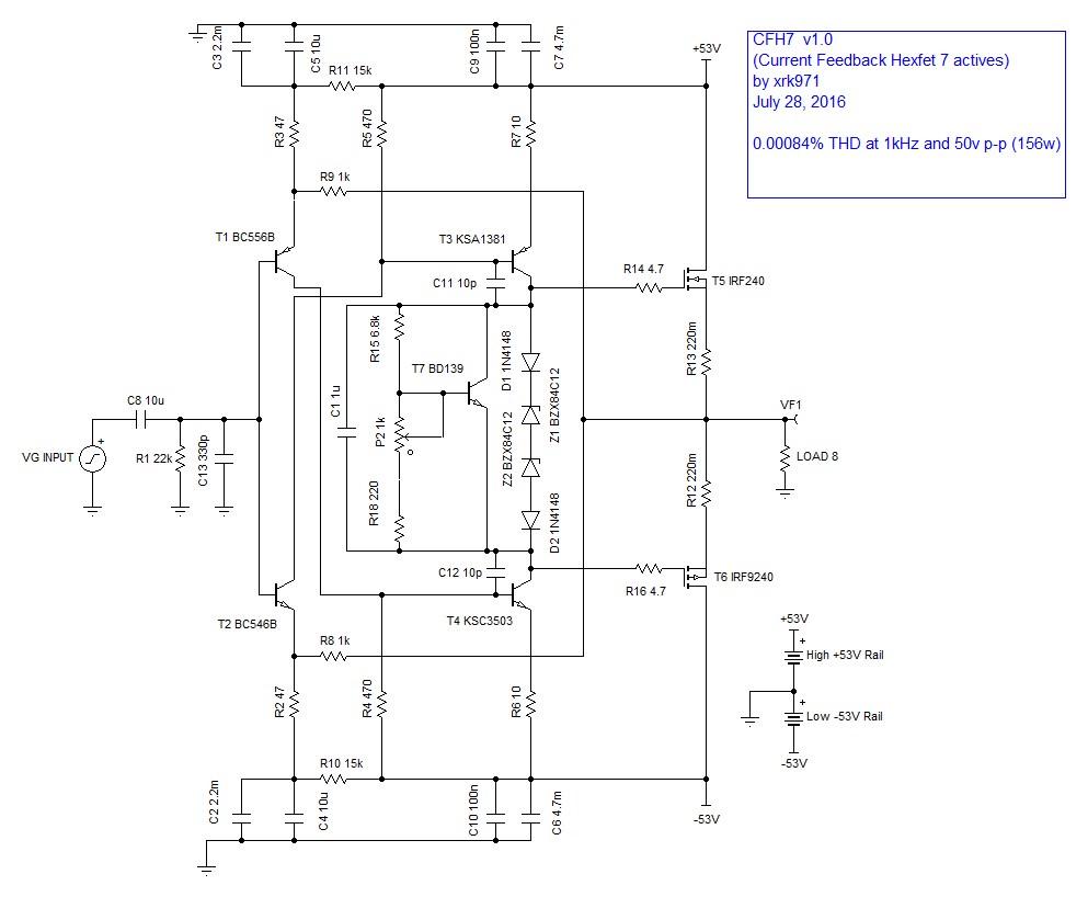
CFH7 - current feedback hexFET amp
Schematic:
Very clean and simple. I had some little questions.
Do you tie the junction of z1 and z2 to the output? It's missing, and without it I don't see how the Vgs is clamped.
Do the 0.22 ohm source resistors do anything? They seem vestigial.
What protects the outputs if speaker leads are shorted?
Very clean and simple. I had some little questions.
Do you tie the junction of z1 and z2 to the output? It's missing, and without it I don't see how the Vgs is clamped.
Do the 0.22 ohm source resistors do anything? They seem vestigial.
What protects the outputs if speaker leads are shorted?
The connection from output to Zeners is missing in this diagram but corrected in the one in the CFH7 thread.
http://www.diyaudio.com/forums/solid-state/294834-cfh7-amp.html
Those 0.22R resistors serve to allow for small differences in IRFP240 vs IRFP9240 responses to be absorbed and balanced. They are also handy for setting bias current.
A short would blow your PSU fuse if you had one.
My AX-20 Build (3 pairs) using QQ12E5K1 pcb.
Hi-Fi sound, with softer treble than AX-14!
You can never get tired of listening music, even at a loud level!
can you please share pcb of ax 20 (3 pairs).
- Home
- Amplifiers
- Solid State
- 100W Ultimate Fidelity Amplifier