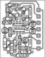
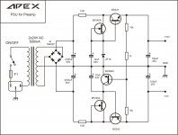
This circuit have +/-15V stabilized output voltage from +/-55V amp rail voltage on input, can be use for preamp PS.
hi sir apex do u have the psb layout for this?
hi sir apex do u have the psb layout for this?
No, but circuit is simple, you can design your own pcb.
hi sir apex do u have the psb layout for this?
Use this PCB for +/-15V regulator.
Attachments
Last edited:
Hi Mr Mile. I agree if you want to share a PCB with a PDF file, I do not measure the dimensions of the PCB again.
unless the schematic and layout of premises component JPG files. Thank you Mr Mile.
I hope that friends and other friends.
unless the schematic and layout of premises component JPG files. Thank you Mr Mile.
I hope that friends and other friends.
Hi Mr Mile. I agree if you want to share a PCB with a PDF file, I do not measure the dimensions of the PCB again.
unless the schematic and layout of premises component JPG files. Thank you Mr Mile.
I hope that friends and other friends.
+/-15V pcb
Attachments
Sorry , I'm a little late into this thread.
What is the distortion of this amp?
There is a lot I concur with. NO Miller capacitors. Crossover distortion should be virtually zero. Many people think that the input capacitor is to roll off high frequencies to avoid/minimise transient distortions. It does this when combined with a series input resistor. It has another major factor which has not been commented on widely. This is to ensure that the input transistor operates with a low base impedance at high frequencies. This improves its stability.
This architecture is the sort I recommend. I have not heard this amp, but I suspect it will sound better and cleaner than many. Which is why I'm interested in its (measured) distortion!
Thanks
John
Some might think that, but the enlightened Members who care to read, have already found out the RF attenuating advantage and the Rs @ HF advantage.Many people think that the input capacitor is to roll off high frequencies to avoid/minimise transient distortions. It does this when combined with a series input resistor. It has another major factor which has not been commented on widely. This is to ensure that the input transistor operates with a low base impedance at high frequencies. This improves its stability.
These messages are posted, but you are right in one respect, many who should know better post "internet facts" and quite a few believe them.
It does not help when National show a schematic without the RF capacitor and without the DC blocking required to make their chipamps AC coupled.
Last edited:
Sorry , I'm a little late into this thread.
What is the distortion of this amp?
There is a lot I concur with. NO Miller capacitors. Crossover distortion should be virtually zero. Many people think that the input capacitor is to roll off high frequencies to avoid/minimise transient distortions. It does this when combined with a series input resistor. It has another major factor which has not been commented on widely. This is to ensure that the input transistor operates with a low base impedance at high frequencies. This improves its stability.
This architecture is the sort I recommend. I have not heard this amp, but I suspect it will sound better and cleaner than many. Which is why I'm interested in its (measured) distortion!
Thanks
John
Do You considering to build this amp? Latest post about sound #695.
Regards
Before that, I thank my many+/-15V pcb
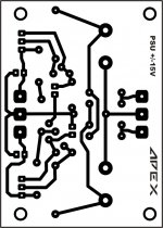
I question why PCB layout is not made Mirror layer?
I think it's easier to move the path to the PCB. thanks
Before that, I thank my many
I question why PCB layout is not made Mirror layer?
I think it's easier to move the path to the PCB. thanks
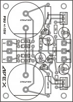
PSU +/-15V mirror pcb layer.
Attachments
thanks mile, I hope soon I will show the project in the forumPSU +/-15V mirror pcb layer.
thanks mile, I hope soon I will show the project in the forum
Project will be +/-15V PSU?
I want to create a power amplifier 80 watts with a flat preamp, to the monitor speakers. I have a suggestion I have to use whatever it takes to build an amplifier. I want to use MM3 plans for a flat preamp and power use ax14. if you have a better idea for the project Mile Mr. monitor speakers that I want this plan. thanksProject will be +/-15V PSU?
I want to create a power amplifier 80 watts with a flat preamp, to the monitor speakers. I have a suggestion I have to use whatever it takes to build an amplifier. I want to use MM3 plans for a flat preamp and power use ax14. if you have a better idea for the project Mile Mr. monitor speakers that I want this plan. thanks
Flat preamp is phono MM preamp with RIAA EQ?
I think not a phono preamp, but the monitor speakers with power aktive 40 watts or 80 watts. like the example image http://images04.olx.co.id/ui/5/85/8...K-KID-6-KOND-95-ADA-DUS-Bekasi-1271903649.jpgSpeaker Terminal can be add to any amp with rail voltage over +/-36V DC and rail fuses. I prefer this protect more than protect with relay.
http://images03.olx.co.id/ui/5/85/8...KRK-ROCK-KID-6-KOND-95-ADA-DUS-1271903649.jpg
Thank you for helping me Mr. Mile 🙂.
Last edited:
I think not a phono preamp, but the monitor speakers with power aktive 40 watts or 80 watts. like the example image http://images04.olx.co.id/ui/5/85/8...K-KID-6-KOND-95-ADA-DUS-Bekasi-1271903649.jpg
http://images03.olx.co.id/ui/5/85/8...KRK-ROCK-KID-6-KOND-95-ADA-DUS-1271903649.jpg
Thank you for helping me Mr. Mile 🙂.
I suggest ML3 for powered speaker preamp.
apexaudio -
I don't think I will build one of these. I've already built a 100W amp, thanks.
Some things couuld be improved, I suggest. For example, probably, you could get lower distortion using conventional Darlingtons instead of Baxandall pairs. I would not use current sources sharing the same bias diodes, even with the resistor on the base (your input stage current source and VAS load).
John
- Home
- Amplifiers
- Solid State
- 100W Ultimate Fidelity Amplifier