Re: Is this better?
That's how I had mine set up. Anonther thing... the 10k is way lower than it should be. 220k is more like it - you don't need to waste a lot in the base bias. The transistor will only dissipate a couple of watts into a short, you sure don't need the bias resistor burning up any more than that.
Back to back trafos is the easiest way yo get isoaled 220V. Don't need a lot of VA.
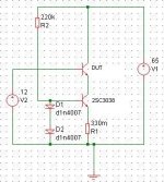
How about adding a 1M0 in series with the DUT to allow measurement of the real leakage.
A Variac on the input would allow you to check how leakage varies with DUT voltage.
Try tying DUT base to DUT emitter with a 10k resistor.
A Variac on the input would allow you to check how leakage varies with DUT voltage.
Try tying DUT base to DUT emitter with a 10k resistor.
Wg_ski,
Yeah you're right!
When designing amp's OP-stage we can past the strict Vceo numbers.
SOA is the most important!
Belive or not, I have some genuine MJ15003s laying here ( I got them directly from ON) and their Vceo is ~240...280V! Datasheet says 140V (min.).
I used ten pcs of them for a 500Wrms/8Ohm subamp project, idle rails were +/-100V!

At 300V rails R2 would dissipate ~400mW (300V^2/220000). Use a 2W rated resistor there! Go for 1/4W as R1.
Say the measured device's Vceo0 is 200V, and the HV PSU's rail voltage is 300V. At 10mA Ic the dissipation of 2SC3038 will be (300V-200V)×0.010A=1W.
Actually your Ic is about ~3.2mA, then heatsink is not required. Increasing safety margin of the circuit I'd apply a small heatsink on it.
And finally, be very-very careful when using the finished and working circuit, 300Vdc is LETHAL!
Thanks Andy. Yes am looking at possibilities of building this in a wooden box for maximum isolation. As for the connections to the DUT am thinking of "dominos" if thats what its called there these are connectors in plastic with screws to hold wires.
Also add a clear red indicator to show the unit is on and easily accessible power switch.
Any recommendations for mains fuse rating?
Just a quick question. Suppose i want to test a transistor like a TIP2955 which has a VCE of 60V if genuine and suppose 30V fake. Could it be done with that circuit?
In case say suppose i have to test a PNP for VCE is the figure below correct.
Thanks
Attachments

zeus_threat said:Any recommendations for mains fuse rating?
Just a quick question. Suppose i want to test a transistor like a TIP2955 which has a VCE of 60V if genuine and suppose 30V fake. Could it be done with that circuit?
In case say suppose i have to test a PNP for VCE is the figure below correct.
Thanks
Mains fuse? Minimum that won't blow from the turn-on transient.
A real TIP2955 will probably test out over 100V. A fake might even go that high. Especially if the fake is actually a real TIP30. You really need to check capacitance or SOA. Just how prevalent *are* fakes on these cheap commodity transistors? I used to think they only did that with premium high dollar devices - until I banged my head for a couple months wondering why my amp oscillated and small signal devices were WAY out of spec.
For PNPs you just switch the leads for BV test. Unfortunately, there's no easy 2-lead swap to test SOA.
Hi thanks for your reply
Is the discussed VCE test (DUT+CCS) enough to determine if the device is fake? Can you please explain the test you are mentionning.You really need to check capacitance or SOA
Sad to hear this had BC546 used in an amp's LTP and had the same problem until i replaced them.until I banged my head for a couple months wondering why my amp oscillated and small signal devices were WAY out of spec.
Wg_ski, good point! You're right again!
From Vceo0 measurement we don't now if a transistor is fake or not!
An example: i've got a pair of genuine Moto 2N3773s with 140...150V Vceo0, and and fake one (Toshiba labeled) that measured 210V Vceo0!
I think a good test would be for example a capacitance test (I never did it indeed).
Bigger die > bigger capacitance.
Am I right, guys?
Andy L. Francis said:An example: i've got a pair of genuine Moto 2N3773s with 140...150V Vceo0, and and fake one (Toshiba labeled) that measured 210V Vceo0!
The Toshiba may or may not be "fake". Toshiba used to make a 2SD873 that *was* a 2N3773. They may have been sold with both type numbers. If it's a real 2SD873, it will be well constructed with a comparable size die. And it would be an old lot from the 80's or early 90's. I have some Toshiba 2N3772's that there is absoluetly nothing wrong with.
If they do the usual putting a 2N3055 die in a TO-3 and labeling it 'MJ15024' it will probably only measure 120V-180V VCEO. If the same thing were labeled 'MJ15003' or '2N5886' you need additional screening to be sure. And some 2N3055's will take over 200V. Rarer, but it does happen.
[/QUOTE]
I think a good test would be for example a capacitance test (I never did it indeed).
Bigger die > bigger capacitance.
Am I right, guys? [/B][/QUOTE]
Either capacitance or a true SOA test.
To measure capacitance the way thet do in the data sheets (under bias) it requires at test jig that applies the appropriate bias and in impedance bridge or LCR meter. Too much trouble to set up. For a quick and dirty test you can use a DMM's capacitance metering function. It will give the zero-bias reading. If yours won't work (or don't have one) set up a 555 timer with the DUT's veb or vcb as the timing cap. Run it on as low a voltage as your 555 will handle - the CMOS version will work at 3 volts. Back calculate capacitance from the frequency. Again, you're just looking for realtive numbers between a know good die and the suspect.
For the SOA test, you have the right idea, but that current source won't hold up. The ones in the Tektronix app note are MUCH beefier. If you're not providing for shut-down on failure, it's way easier to use a power resistor in the emitter. 11 volts at 4 amps, for example is 44 watts (2.7 ohms, BTW). You only need to turn it on a second or two (before your DUT starts really heating up) so a 20 watt resistor will be good enough. But a 5 watt won't, and certainly a small transistor won't.
For the SOA test, you have the right idea, but that current source won't hold up. The ones in the Tektronix app note are MUCH beefier. If you're not providing for shut-down on failure, it's way easier to use a power resistor in the emitter. 11 volts at 4 amps, for example is 44 watts (2.7 ohms, BTW). You only need to turn it on a second or two (before your DUT starts really heating up) so a 20 watt resistor will be good enough. But a 5 watt won't, and certainly a small transistor won't.
Thanks wg. I'll check around to see if they have high power resistors. Otherwise what if i parallel 2 or 3 of these 2SC3038 each with its own resistor in the emitter could that be better?
For the supply to the DUT CE how many amps would the transformer need to be rated approximately? Got a 25-0-25 125VA around would that be ok?
Am thinking of something since i have to measure capacitance. Could speaker workshop be used with carl nagra's jig. I already have one built which i am using. Its not hanging wires its in a box with proper switches. Its looks like a wallin jig but has the heart of carl nagra's setup 😀
Is it possible to do that? In case yes can you briefly exlpain how i would connect the dut to the jig
Thanks
The CCS will only have 12 volts or whatever on it. What you want is a big sucker that has high beta at high current and can handle things when the DUT fails. A couple paralleled 2N3773's on a good size heat sink would do the trick. Bring the base bias for the CCS from the 12V supply - you want about 5-10% of the CCS current through that resistor - 220k won't work here. It sure is easier to just use a resistor. You only need to test the DUT for a second or two. It won't hurt anything to overload the VCC supply by even 5x for that short a time. But the VCC will be the *loaded* voltage, which drops more with smaller trafos. I have a 0-65V lab supply so problem solved. If you use a lab supply, you can set its current limit just above the CCS value and a then DUT failure in not always catastrophic.
Speaker Workshop to measure capacitance? Never thought of that. It might not be able to measure 1000's of pF - the measurements may be in the noise. And you would need to keep the signal level low - 0.7 volts peak and no more.
Speaker Workshop to measure capacitance? Never thought of that. It might not be able to measure 1000's of pF - the measurements may be in the noise. And you would need to keep the signal level low - 0.7 volts peak and no more.
Thanks you're right a coupe of resistors is way simpler and cheaper. I don't have any lab supply handy so i'll need to build two PSU's since i got the transformers. Will these do for the 2 PSU:-
25-0-25 125VA rectified to get around 65V
What current rating would you suggest for the 12V psu. Will a 500mA do or else i have a 12V 5A handy?
I'll do a quick test with speaker workshop (no power amp in output) as a dirty check and see. Suppose i measure x pF as capacitance how do i proceed next?
25-0-25 125VA rectified to get around 65V
What current rating would you suggest for the 12V psu. Will a 500mA do or else i have a 12V 5A handy?
I'll do a quick test with speaker workshop (no power amp in output) as a dirty check and see. Suppose i measure x pF as capacitance how do i proceed next?
The 25-0-25 will do ok for the VCC. For the 12V, jou just need base current. Ic divide by beta. Make sure that supply has reverse polarity protection (can tolerate having overvoltage dumped into its output). Something with built in protection diodes.
If you're trying to test 100's or 1000's of pF with SW, first make sure you *can*. Try testing a 1000 pF fixed cap and see if you get a good reading. You *cannot* skip any calibration steps - for doing speakers I usually skip measureing sound card input capacitance. Don't do that here. Compare 'suspect' devices to a known good one, because you're testing at zero bias, and the numbers may not be what's quoted on the data sheet.
If you're trying to test 100's or 1000's of pF with SW, first make sure you *can*. Try testing a 1000 pF fixed cap and see if you get a good reading. You *cannot* skip any calibration steps - for doing speakers I usually skip measureing sound card input capacitance. Don't do that here. Compare 'suspect' devices to a known good one, because you're testing at zero bias, and the numbers may not be what's quoted on the data sheet.
Thanks wg. I'll use the 12V 5A better have more in reserve plus i purchased that specifically for testing should do the job. If i understand properly this 12V supply has to be made variable to adjust for DUT collector current right?
Now in case i test devices rated less than those MJ150xx and since my VCE supply is fixed, i need to adjust base voltage to drive these to lower collector currents according to the SOA in their datasheets right?
For speaker workshop i remember having measured 1uF, 100nF and 22pF quite accurately. For the DUT what do i have to measure BE capacitance?
Thanks
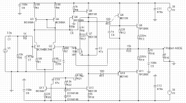
zeus_threat said:Back after some time. Attached figure is version i will be going for. Note bc546/556 repalced with 2n5401/2n5551. TIPs replaced with mj15003/04. Any comments welcome.
Thanks
Whew! A lot of work to select transistors for a 60 volt application!
 . I think even fakes would have worked.
 Don't forget the base stopper on Q12 unless you want to put DC to the speaker when it clips.
- Status
- Not open for further replies.
- Home
- Amplifiers
- Solid State
- 100W peak 4Ohm